It is difficult to find a girl or woman who would not use a hair dryer to dry her hair, especially in the cold season. And this is understandable, since long hair needs to dry well at room temperature, it takes several hours, and with the current pace of life it is a luxury.
Therefore, these devices have been, are and will always be in demand. And this is proved by statistics on sales of hair dryers as a gift to women on various occasions. It is these devices that occupy one of the leading places, since the thing is necessary and inexpensive.
But no matter how high-quality the product is - elevated temperature, high consumption current, and, as a rule, improper operation, often lead to breakdowns of household hair dryers.

And before buying a new device, you can try to return to the "life" of an old friend. Moreover, the breakdown can be minor and easily fixed.
Below, one of the most frequent breakdowns of hair dryers and a method for eliminating it (using the “Startex” hair dryer as an example) will be described in detail.
Of the tools you need only those that are in almost every home. The only thing that may not be is a multimeter or some other device showing a circuit. But for sure, a friend or neighbor has it, and you can ask for a repair. If you still don’t have a good neighbor or electric friend nearby, you can buy the cheapest multimeter, especially since there are enough of them on the market. In the future, it will definitely come in handy, for example, to check a light bulb, battery or mains voltage.
In the photo (Figure 1), a hair dryer having a problem in operation.
It lies in the fact that when turned on at maximum power, it does not react in any way.

The hair dryer itself has three switch positions:
- The lowest is “OFF”.
- Average - half the heating power.
- Upper - maximum heating power.

Most often in the upper position, a hairdryer is used, as it provides the fastest drying possible. Therefore, ignoring such a breakdown is unacceptable.
So, to find the cause of the malfunction, it is necessary to disassemble the device. Start with the pen.

It has a position switch and two mounting screws for a Phillips screwdriver.
We put the hair dryer on its side, and unscrew these two screws.
Next, with some effort, remove one of the side parts of the handle.

After removing the cover, you can see its filling.
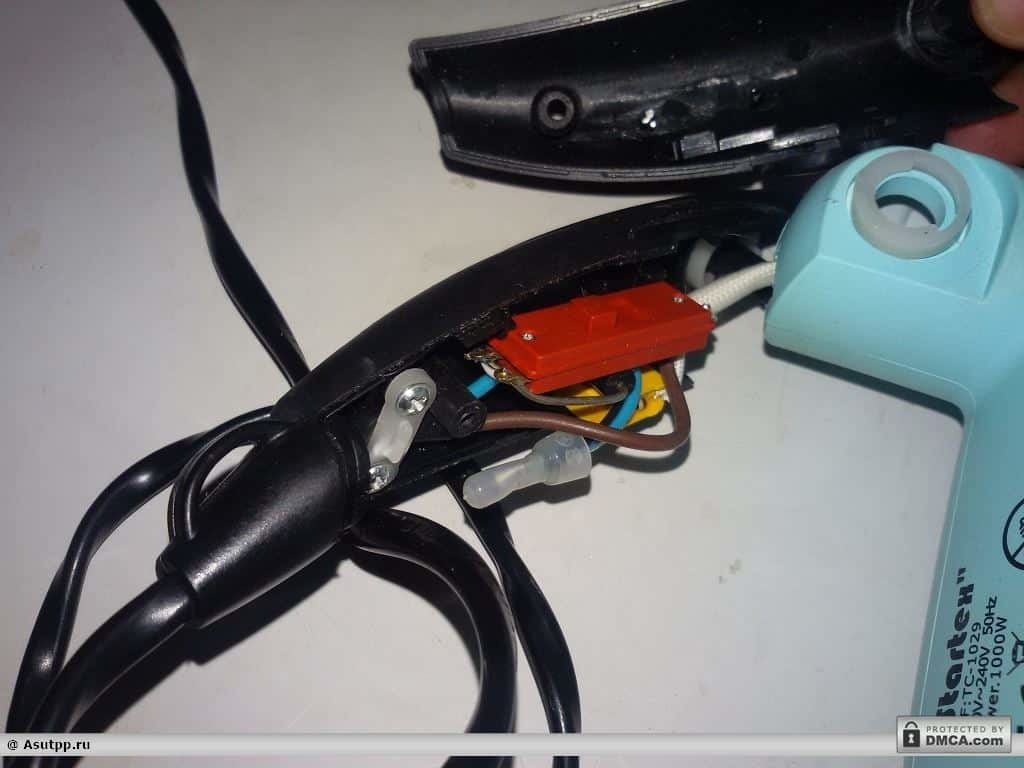
Here are: switch, diode, capacitor, zero (common) clamp and clamp for fixing the cord.

The zero clamp is located inside the dielectric cap (Figure 7).
It connects: a wire from the power cord - blue, a black wire that goes further to the heater, and one terminal of the capacitor.
The position switch has three outputs. One common that comes with a phase brown wire from the power cord.
On the other hand, a diode is soldered to the terminals.
If you look at the circuit diagram (Figure 8), you can see that in one of the positions of the switch, the current flows to the heater through the diode. This reduces the heating power and corresponds to the middle position of the switch.

When the second or both contacts are closed, the current passes to the heater spiral, bypassing the diode, which corresponds to the maximum power - the third position.
The capacitor is used to dampen the noise generated by the motor into the network. This capacitor can be dismantled altogether. Then there will be more space in the pen, and it will not explode with increasing voltage in the network.
When examining these components, you should pay attention to their external condition. There should be no damage, soot, breakage of conductors and deformation of the case from the temperature regime.
If all the wires are in place, you need to pay attention to the switch. This is a weak link in the circuit, since the mechanical movement of the contacts takes place in it and when they open the electric arc, forming carbon deposits on their surface.
You can check the integrity of the diode, but in this case there is no need to do this, since at half the power, the hairdryer works, which means the diode is intact.

Check that the current flows through the switch.
To do this, we connect one end of the device to test the circuit to the common terminal, and the other to the terminals on the opposite side.
But you need to do this with a certain switch position.
First, connect the device where only the diode is soldered, and put the switch lever in the middle position.


The indicator shows the circuit. So, the contacts inside the case are closed and this is good.
Next, we rearrange this probe to the second output, where, in addition to the diode, a wire is soldered.
The switch must be set to its highest position (Figure 12).


The device does not show the circuit, so something happened with the contacts. Fortunately, the switch turned out to be collapsible. The upper and lower parts are fastened with two screws.
They must be carefully unscrewed. A screwdriver will help here, and not necessarily a cross. An ordinary straight line with a small tip, for example, a watch, will do.
The screws are tightened quite strongly, so you will have to make some effort. You need to be extremely careful, the screwdriver is thin and can cause deep injury when slipping. Therefore, it is better not to put your fingers under the switch.
For convenience, you can remove the entire filling by unscrewing the cable clamp.
Now you can rest the lower part of the case against the table and push the screwdriver onto the screw (Figure 14).

In this way, small cogs can be easily unscrewed. When both screws are removed, carefully remove the top cover of the switch with two fingers.

Below it is a switch handle, on the back of which a special relief is cut, thanks to him, there is a pressing or raising of contacts at a certain position of the lever switch.

A hole is made in the center of the handle for a spring, which, together with a metal ball (Figure 16), provides step-by-step switching of modes. When disassembling, make sure that the spring and ball are not lost. They should immediately be put, for example, in a matchbox.
Next, we move on to inspecting the contacts (Figure 17).
Fixed, located at the top, and moving have a springy structure, due to which, the contacts are closed if they are not affected. When switching modes, the “cams” of the lever press on these contacts, and they, under their influence, fall down and open.

If you look at the contacts from the side (Figure 18), you can see that the neighbor did not return to its original position to close the circuit.

It is this contact that is responsible for turning on the maximum heating power that did not work.
Below in the photo, you can see how the contacts work. When you click on the distant contact, it bends.

If you let him go, then he comes back and closes the circuit.

We do the same with another contact.

Down, it is pushed, but does not return anymore (Figure 22).

Most likely, a flexible conductor with a contact rubs against the side inner wall of the switch housing and locks in the lower position. This is the reason for the incorrect operation of the device in one of the modes.
To return the switch to normal operation, you must perform the following sequence of actions:
- Gently squeeze the contact block with “ducklings” or small pliers. This will give the contact more free play in the groove of the switch housing.

Fig. 23. Compress the contact block - Additionally, you need to process the edges of the flexible conductors with a file. To do this, the contact area itself can be removed. So it will be more convenient to process them.

Fig. 24. Clean the file edges of the conductors - Also, a file - we clean contacts from a deposit.

Fig. 25. Get rid of soot - We put the contact pad in place.

Fig. 26. Put the site in place - For better glide, lubricate the inner walls of the housing with lithol.

Fig. 27. Litol at the tip of the cutter 
Fig. 28. Lubricate with lithol.
Now you can check how the progress of the contact has improved. Finger click on the contact, and release it.

It can be seen that the contact now works fine, and nothing interferes with its progress.
Next, you must insert the spring (Fig. 30) into the hole of the switch handle.

It is better to insert a metal ball into one of the grooves on the body (Figure 31). So it does not fall off the spring when installing the switch handle.
The important thing is which side to put the handle of the switch on, as the correctness of its operation depends on this.

When the correct side is determined, turn the lever so that the center of the spring hits the ball, and not to the side.

Holding the handle, we put on it the upper part of the switch housing.
Without releasing the cover, we tighten the two screws of fastening (Fig. 33). Now the switch is ready, and without collecting the hair dryer, you can check its operation in different modes.

Since the live parts are open, the switching of modes must be done with the power plug disconnected from the mains. And only after switching, apply power.
If everything works, you can assemble the device. But if you want, you can make an audit of the working part of the hairdryer and the contacts of the temperature sensor.
To do this, unscrew another screw and remove the rear grill.

Next, using a knife to separate the two parts of the body.


Spreading two halves with your fingers, we extend the engine with a heater. They may have debris and hair that needs to be removed.

We find the contacts of the temperature sensor and clean them with a file.

After, we insert the heater back, making sure that the gasket from the heat-resistant material remains in place.

We snap the rear grill and tighten the screw.

Next, insert the switch into the special grooves, making sure that the square of the control knob sits exactly on the “flag” of the switch. We lay the wires in the lower part of the handle, and put on its second half.


Tighten the screws and check the operation of the device.

On this, the hair dryer repair can be considered completed.
Video tips and instructions.
- How to make a refrigerator repair with your own hands?
- How to make a do-it-yourself infrared heater repair?
- How to repair a multicooker with your own hands?
- How to make an iron repair with your own hands?