Infrared heaters in everyday life are used quite recently, but they have already managed to prove themselves. as sufficiently effective devices that can provide comfort and coziness in a small cool indoors.
A feature of these devices is the ability to heat surrounding objects, not air. For example, electric fireplaces with an open spiral, heating the air, burn oxygen, which can lead to difficulty breathing and headache. Infrared heaters do not have this drawback. Also, from the advantages of these devices, it can be noted light weight and fairly reasonable prices. It is not surprising that these heaters have become very popular nowadays, both for use at home and in production.
Like all heaters, these devices consume significant current, which over time leads to the inevitable breakdown of the device. When this happens depends on various factors, for example, the duration of work during the day, the power mode used, as well as the quality of the product.
In this regard, it would be useful to know the weaknesses and causes of frequent breakdowns of infrared heaters.
In this article, we will talk about the "standard" breakdown of an infrared device and a method for its quick and high-quality repair.

Here, in the photo, a heater with a clear problem in operation. The device does not react to inclusion in the network. The rotation of the thermostat knob also yielded nothing. It became clear that the disassembly of the heater can not be avoided, since the problem is clearly located inside. Repair should begin by removing the side cover, the one from which the power cord comes out.

But, to do this, it is necessary to unscrew the two fixing screws and remove the thermostat knob.

The handle is easy to remove, just pick it with a screwdriver and pull your fingers towards you. When the two side screws are removed, it is necessary with one hand to grasp the metal casing of the heater, and with the other pull the cover to the side.

To make the plastic cover easier to remove, when tightened, it must be slightly swayed from side to side.

This can help if the lid is slightly adhered due to the heating of the metal casing. When the side part is removed, you need to be careful not to break the wires and not break the thermostat tube.

Gas is pumped into the tube, and if it comes out when it breaks, the thermostat will not perform its function, that is, it will not turn off the device when it is overheated.

In the photo, the thermostat itself is visible, with a suitable tube to it, as well as other circuit elements, such as wires, terminals and the electrical output of the heating element.

If you look at the diagram, then the brown wire coming out of the power cord goes to the thermostat. Further, the red wire emerging from the thermostat supplies voltage to the second terminal of the heating element, which is not visible from the disassembled side.

The green-yellow wire is used to ground the housing, and it is screwed securely to the metal housing of the device.
Another wire coming out of the cord is blue. According to it, the mains voltage is supplied to the output of the heating element, which is located with the open side.
It was he who was burned out. The reason for this could be poor contact, due to loosely tightened nuts, at the heater outlet.

In this case, in order to qualitatively make the connection of wires, it is necessary to bite off the problem area of the cable and cut it again. To do this, you need to add the length of the cord inside the case, otherwise it will be missed.
Retract the cable prevents a special latch, which is installed at the entrance to the housing.
It works on the principle of clamping and to pull the cable inside the case, it must be disassembled.

To do this, from the outside, pry the latch with a screwdriver and pull it out with your hands.

When it comes out, it can easily be divided into two parts, which will allow free movement of the cable.

It is very important to remember how this latch stood, because when assembling the device in the reverse order, there can be difficulties. Continuing work, we pull the cable in and bite off the problem area.


Next, disconnect the grounding, yellow-green wire.

Also, remove the brown wire from the thermostat. After disconnecting all the wires, we throw this “spider” out of the wires, after having bitten off the clamp, for connecting to the temperature regulator.

Bite off the clamp so that a little copper wire remains on it.

If the farm has the same new clamp, then it is better to put it, otherwise this one will do. We heat the soldering iron, and with the help of tin and rosin, solder the cut-off clamp to a new, stripped brown wire.

The place of soldering should be insulated with some heat-resistant material, for example, cotton tape. After preliminary stripping the output on the thermostat with a file, we fit a new, just sealed clip on it.

Now you can do the grounding. It would be nice to find a suitable tip and use it to connect the wire.
Well, if there is no tip, then you can simply make an eyelet from the stripped wire and screw the grounding to the body through a wide washer.

Next, the most important thing will go, namely connecting the wire to one of the terminals of the heating element.
In fact, this is the elimination of the problem that was formed initially and it must be done in a quality manner so that it does not work out as it is now.
As can be seen in the photo, carbon deposits formed at the junction, due to heating, which may impair contact. Therefore, to emphasize the copper loop, it is better to use a new washer, leaving the old one in place. A washer with a small width is suitable for this, since if you use the standard, the thread of the heating element may not be enough.


We wind a new washer onto the thread with a wrench, with little effort.

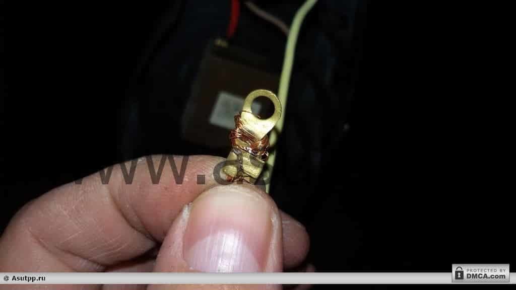
Now we clean the blue wire so that you can make a loop. If there is a corresponding tip, then you can use it. Such a connection would be even better than a homemade loop.

But as practice shows, at home, tips are a rarity, so a loop is used in this description. We make a loop, and without fail it should be along the thread, so that when tightening the nut, the wire does not go apart. The end of the loop must be twisted into a lock. This will also prevent unwinding of the wire.
Following the loop, put on a wide washer and clamp it with a nut.

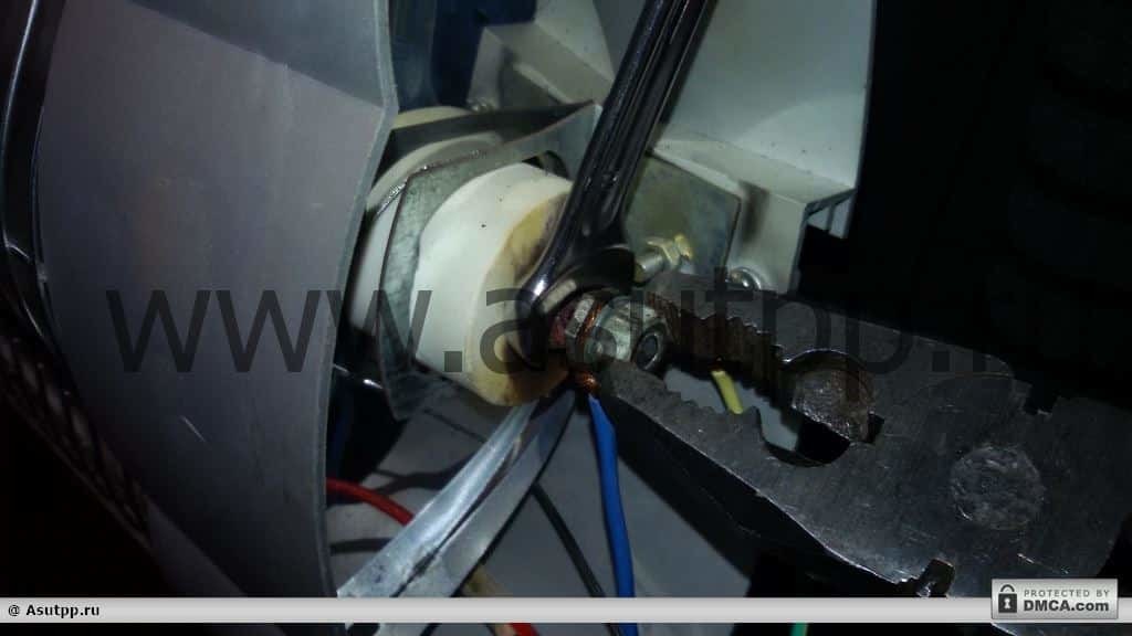
For good contact, we use two keys, one hold the nut closer to the heater, the other clamp the washer with a loop.
Instead of the second key, you can use pliers, so you can feel the force of clamping. When using a key, this force can be exceeded and the threads of the heating element can be broken, which will not be very good.
When all the ends are clamped, pull the excess cord out and put on the clip.

We insert it into the plastic case and lay out the wires inside so that they are as far away as possible from the heating element.


If the thermoregulator tube is removed, we insert it into the upper slot, between the body and the reflector.

Now it remains to put the side cover on the case, tighten the screws and install the knob on its axis.


We turn on our infrared heater and turn on the knob to check its operation.

As seen in the photo, the infrared heater glows and works great.
In conclusion, I would like to note that repair does not require anything complicated, nor any special skills or a special tool, but only straight arms and the desire to do the work yourself, everything else is necessary will work out.
- How to make a refrigerator repair with your own hands?
- How to repair a multicooker with your own hands?
- How to make a hair dryer repair with your own hands?
- How to make an iron repair with your own hands?