At first glance, connecting the hob to the power supply yourself seems to be a rather complicated procedure. Having bought an expensive device, not everyone will also master the services of a master, the price of which in Moscow starts from 1000 rubles. In our article we will try to answer the most popular questions that arise during installation. And then your connection will go through like an experienced electrician.

Safety regulations
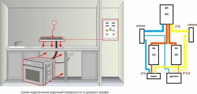
The connection of the electric hob and oven, like any powerful technology, always takes place via a separate wiring line from the switchboard. The oven must not be powered from a common box in the kitchen or from existing outlets.
Attention! Earned on our website kitchen designer. You can familiarize yourself with it and design your dream kitchen for free! May also come in handy wardrobes designer.
A conventional circuit breaker will not be able to protect the device in the event of insulation damage and electrical leakage. Please make sure the wires are in good condition before installation. Otherwise, the stove will constantly turn off and become unusable. And do not forget to turn off the machines on the dashboard.
Wiring cable for connection
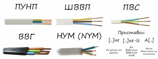
To do this, use a power cable of two types: VVGng-Ls or NYM. In the first, the conductive core is protected by PVC compound and on top by another, non-combustible. And secondly, under the cable sheath, the cores are filled with belt insulation.
The cable must be copper and three-core, with a cross-section of at least 6 mm2. It is with its help that you can connect all existing models of hobs.

Connecting an induction hob in a flap
The hob and oven are connected only through an RCD and a diffusion machine or a differential machine with a leakage current of 30 mA. Do not connect the hobs through a conventional machine with a thermal release.
If the cable has already been installed, but has a smaller cross-section than is necessary for the power of your hob, and you do not want to re-route it, there is a way out. It is possible, to the detriment of the panel's power, to do the following - install a switch in the panel according to the nominal cable cross-section. In this case, the stove will not work at all and it is impossible to turn on all the burners in it at the same time.
How is the hob connected?
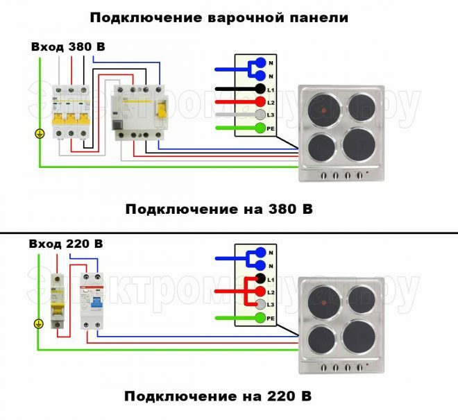
- In the shield, the phase wire of the cable (usually brown or gray, less often of other colors) is brought to the lower terminal of the machine with the number 2.
- The blue (zero core) is connected to the lower terminal, marked N.
- The green-yellow conductor, which is a protective earth, is connected to a similar one, located separately.
Hob socket and plug
The branch and plugs need special ones for currents in the range of 32A-40A. If you will not lead the cable directly into the panel, then you should make a separate socket for it - this is the most convenient option when using the device. Always de-energize the panel during wet cleaning. If your device is connected directly, you will have to turn to the panel several times and turn off the electricity throughout the apartment. And with an outlet, things will go much faster.
The socket is installed at a convenient height for the user, most often no higher than 90 cm from the floor. Do not place the hob on the same level with the socket, so that the appliance rests directly on it. It should be positioned to the right or left.
If there is an oven nearby, the socket should be lower than the oven. Most often, it is placed near the kitchen legs (at least 10 cm from the floor). But it is also impossible to make an outlet on the floor at all, since there is a possibility of flooding by neighbors or a water pipe leak.
The main disadvantage of these outlets is that they stick out from the wall up to 7 centimeters. Therefore, the hob itself will protrude very strongly forward.
Which socket should I choose? Low-power panels up to 3.5 kW (most often two-burner) can be connected via a European socket. But it will always work at maximum (rated power 16A) and get very hot.
But it is quite difficult to put a 3 * 6 mm cable on the plug contacts. The best option would be to use highly specialized plugs and sockets for 40A cookers. How zero and phase are located in the outlet does not matter. The main thing is that the grounding conductor makes contact directly. When connecting the plug, the polarity must be observed; for this there is a special terminal marking.
If you purchased only the plug itself, then you cannot do without a three-core PVA wire, whose section must correspond to the power of the stove. To connect the wire, you must disassemble the plug body, remove the insulation, strip the cores and press them with the NSHV tip. Then tighten the screws on the plug, bring out zero and phase under the side terminals, and grounding under the top screw.
Panel connection without plug
If such a socket does not suit you and you want to remove the junction box or socket, you can do this using two options: sleeves or through a mounting box.
Connecting the electrolux 4-wire hob to a three-wire socket may surprise you at first. The fact is that in many cooking surfaces, cables with four cores are designed for both single-phase 220V connection and two-phase, 380V. It is very convenient that half of the burners can operate on one phase, and the other on a more powerful one.
The second phase can be used not only for control supply. If you want to connect everything to ordinary 220V, you just need to remove one core (black), insulating it. And then you will have zero, ground and phase. It is also possible to connect two phase conductors through one lug.
Very rare, but there is an option with a 5-wire cable. They are designed for 380V and are used for powerful panels from 7 kW. And in order to connect them to our 220V network, you should connect 2 cores in pairs and insulate one. But such a connection will not be entirely correct, since the protective conductor must be of the same cross-section with the phase.
Sleeve connection
In this case, the wires in the socket are connected to the cable that goes to the panel. It is very important here to choose a GML sleeve of the appropriate section.
The sleeves are made of electrical copper with a tin-bismuth coating and are designed for wire and cable of flexibility class 5 and 6. The insulation is tinned and provides corrosion resistance. If the cross-sections of the cores are different, then on the smaller side the sleeve should be sealed with an additional wire. After that, the ends should be pressed in and insulated with a thermotube or electrical tape. Then it all hides in a socket box.
This method is not very convenient because the connection is non-separable and pressing tongs are needed to crimp the ends. It is impossible to crimp the veins with pliers.
Connection via back box
The KlK-5S junction box is the most convenient option. No tools are required other than a screwdriver, and the outgoing cable can be easily disconnected at any time. True, the contacts here are thin and strong tightening can damage them.
But the box is small and it is convenient to mount it anywhere. They are often assigned to kitchen cabinets. Connection is carried out according to the classic scheme:
- blue wire (zero) through terminal N,
- grounding - yellow-green core,
- on the top there are 3 phase connectors.
With a voltage of 220 Volts, the excess phases should be removed and insulated.
Induction hob connection diagrams
How to connect an induction hob? Wiring diagrams vary from manufacturer to manufacturer. But on the back there is always a sticker with the factory drawing.
Scheme for a single-phase network - 1 N. In this case, the first three terminals and the last two (4 and 5) are connected with jumpers. Electrical conductors (copper or brass) are supplied with the hob. Usually they are located together with the terminals and only part of the induction furnace will work without them. And if during operation one of the jumpers burns out and half of the hob fails, you should know that the question is in the jumper.

Before connecting the PVSh wire, it is necessary to remove the insulation and crimp the conductors. Also pay attention to whether there is free space in the terminal box for mounting other lugs. Sometimes they should be shortened or dropped altogether.
First, the jumpers are installed, then the phase is connected to terminal 3 and the contacts are tightened. Zero is mounted on a jumper between 4 and 5 terminals. A blue zero is inserted into the fifth terminal, and the contact is tightened. And the protective ground is connected to a similar connector located separately.

Frequent connection errors
Some miscalculations when connecting the hob are quite serious. They can completely damage the hob or cause a fire.
- Sometimes it happens that the panel starts to work strangely: first it turns off, then turns on on its own. Do not think that it is a matter of incorrectly connected wires. Many models have child protection, which is triggered when buttons are pressed chaotically. There are also models with a cookware recognition function - as long as there is no pan on the burner, the burner will not heat up.
- Another common problem is that only half of the cooking zones work, while the rest show residual heat. In this case, the network blocking is triggered when three-phase models are connected to one-phase. This way the hob limits the power itself. In this case, you should understand the instructions and only then touch the terminal blocks.
- It is forbidden to connect induction panels with a power of more than 3.5 kW through a conventional plug and socket 16A.
- A 2.5 mm cable cannot be used for hobs with a power of 7 kW or more.
- If there is no phase jumper on one of the terminals, then half of the burners will not work, or the panel will not turn on at all.
average rating 0 / 5. Number of ratings: 0
No ratings yet. Be the first to rate.


