Face with the replacement of the switch or connecting the outlet in the household comes up quite often, so everyone should have at least minimal skills to maintain the home electrical system.
We will try to figure out how to make the installation of electrical wiring with your own hands, focusing on the standards of PES and observing safety precautions. Also in this article we will look at the specifics of drafting a project, the rules for introducing electricity into a house, and the subtleties of a reliable wire connection.
The content of the article:
- What is required for home wiring?
- Recommendations for making a wiring diagram
- Is power consumption important?
- Rules for entering electricity into the house
- Wire Connection Rules
-
Wiring instructions
- Stage # 1 - electrical wiring layout
- Stage # 2 - Wall Chipping
- Stage # 3 - installation work
- Stage # 4 - Installation of Installation Boxes
- Stage # 5 - Connecting Outlets
- Stage # 6 - Installation of the lighting system
- Stage # 7 - switchboard device
- Security measures when installing electrical wiring
- Conclusions and useful video on the topic
What is required for home wiring?
The first step is to understand the structure of the electrical network. It consists of electrical points connected with each other and with a power line of various kinds of cables and wires, protective devices and circuit breakers, and a ground loop.
Do not confuse wires and cables. The first ones are conductors for internal wiring, which can be single- and multi-conductor, the second ones consist of several wires united by a common protective sheath.

With an independent electrical wiring device, a huge store of knowledge and skills is needed: from calculating the wire cross section to the skills of twisting the wires and installing the wiring boxes
Cables can be mounted in the ground, under water, in concrete structures; They are also used for home electrical devices if you need to connect high-power appliances or special protection.

The colors of the wires are not accidental, it is defined by the rules of PES. Not everyone follows the recommendations for proper connection, but as a result, it greatly facilitates further repair work
Wire conductors are made up of metals that conduct electricity well: copper and aluminum.
Copper is considered a more valuable material for several reasons:
- has a high current density;
- differs in wear resistance and endurance on a break;
- has less resistance to oxidation;
- does not shrink like aluminum, therefore does not form gaps in the joints.
For internal stationary wiring, it is recommended to use single-core copper wires that are stronger and more reliable than multicore analogues.

Stranding copper wire with aluminum is an unforgivable mistake. These materials have different characteristics, so the contact between them will never be strong and safe. If necessary, use adapters - steel terminals
Types of cables and wires for electrical work:
- VVG (from 1.5 mm² to 10 mm²) and its equivalent NYM - both are multifunctional;
- PVA - to connect lights;
- PW1 - for electric boards;
- PW3(6 mm²) - for mounting the SUP.
Varieties of VVG may also be helpful: VVG-P (flat), VVGng (A), VVGng (A) -LS and etc.
In addition to the choice of wires or cables, it is important to understand the grounding systems that guarantee the safe use of electrical appliances. In a private house, the installation of a ground loop is mandatory; in urban apartments, the bath and household appliances are usually grounded.
There are several strict rules: for example, you can not connect ground wires to metal communications or to do independent work in the switchboard.
Installation of the RCD and circuit breakers, as well as any installation work in the electrical panel is better to entrust qualified electricians who have approvals. They will be able to correctly determine the load and pick up a circuit breaker.
Recommendations for making a wiring diagram
The drafting of intra-house or in-house wiring is a responsible and complex matter requiring qualification. There are many principles and standards for the installation of wires, switches and sockets.
Here are just some of them:
- wiring is better divided into groups - outlet, lighting, etc., highlighting the individual lines under the powerful electrical engineering;
- in the drawing, you must specify the power points and the installation location of powerful energy consumers (oven, air conditioner, washing machine);
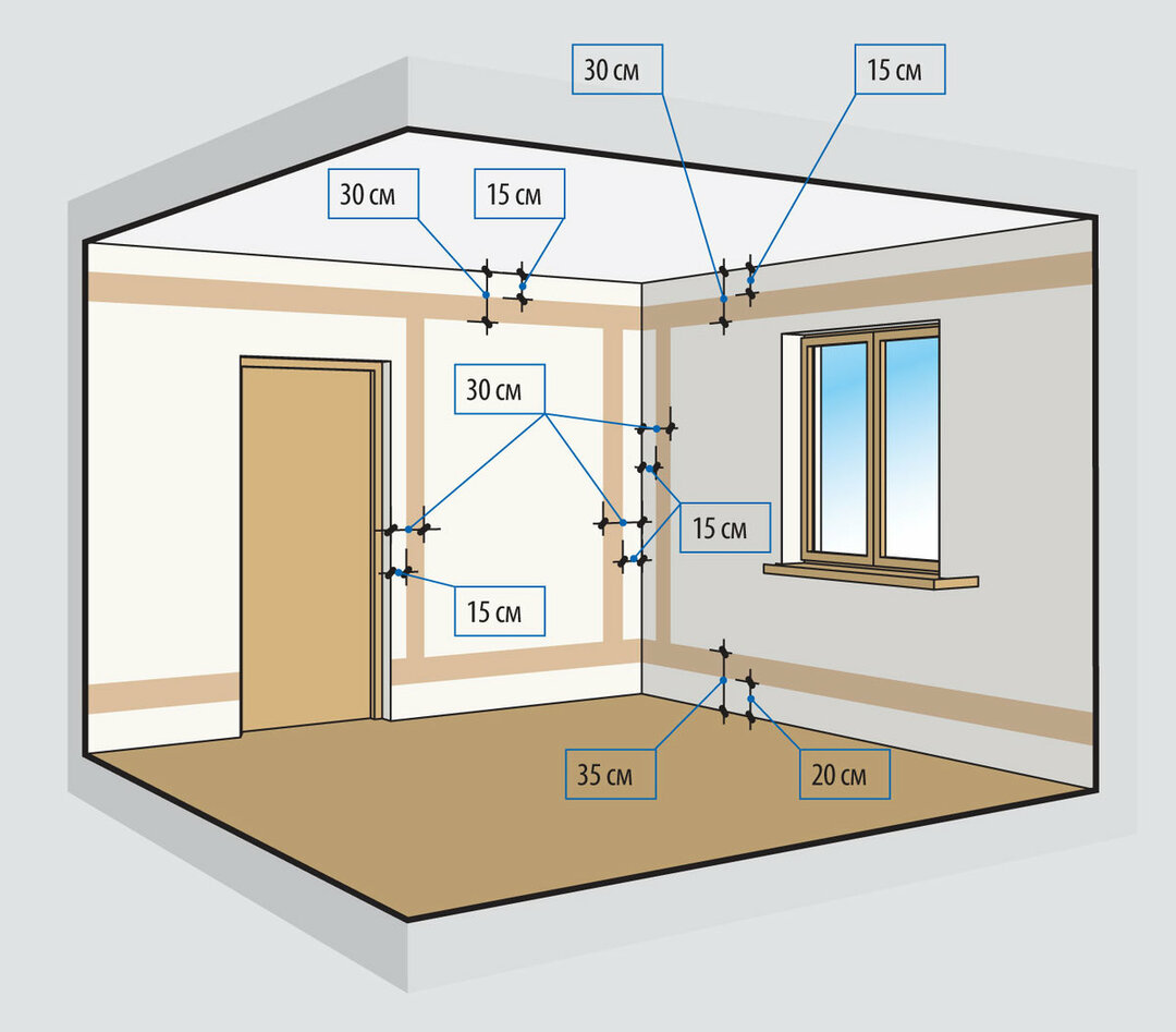
- the location of the outlets - from 0.3 m to 1 m from the floor;
- optimal mounting height of the switches - 0.8-1 m from the floor;
- better more outlets - no extension cords are required;
- a separate project - for a low-current system (for protection against interference, wires are drawn separately from power lines, with an indent of at least 0.5 m);
- bathroom switches lead into the corridor, etc.
It is very important to properly lay the wiring itself - internal or external (open / closed). We recommend to get acquainted with electrical wiring design rules in a private house.

The wiring diagram: the wires should not intersect with various engineering systems, and should be laid only horizontally and vertically. The safest place to install the lines is under the ceiling, from where the vertical lines go down to the outlets and switches
The wiring diagram must be stored, it will definitely come in handy during repairs.
If you have doubts about your own experience or skills, it is better to contact a specialist - qualified electricians. They are familiar with many small, but important nuances that a simple man in the street cannot take into account due to his inexperience.
An experienced designer will competently draw up a wiring diagram, take into account the standards and requirements of the EMP, will produce calculations, selects the equipment of a suitable denomination and, in the end, will take all the responsibility on yourself With self-design and installation will be responsible for the mistakes of the owner of the property.
Is power consumption important?
In addition to design, it is necessary to take into account such a moment as the power consumption in the house.
In a high-rise apartment building, they are usually standardized, but in a separate cottage in front of approval of the documents will need to know what kind of allocated capacity to request from the supplier electricity.

This table will help you determine the total power consumption. It shows the averages for various household appliances and power tools, more accurate data can be found in the equipment data sheets
It is a mistake to assume that the total power consumption is the sum of the individual powers. Simultaneous switching of all devices into the network does not actually occur, therefore, in calculations it is necessary to use such a value as the coefficient of simultaneity.
For sockets, it is a maximum of 0.2, that is, at the same time usually no more than 20% of the power points are involved.
Rules for entering electricity into the house
For private households such an issue as the input of electricity to the house is important. Usually it is carried out using self-supporting wire CIP.
If the power transmission tower is located less than 25 m from the house, additional pillars for support will not be required.

The wire usually stretches to the electrical panel with RCDs, automatons and connection to the ground loop. The transition to a home cable (for example, VVGng) usually takes place in another shield - with metering devices
Input Requirements:
- if the length of the wire is more than 25 m, additional supports are required (in the near pole to the house a shield can be installed, and a grounding loop should be buried close to the ground);
- the height of the wire stretched between the supports is at least 2 m above the ground;
- if the wire crosses building structures, it is mounted in a protective pipe;
- the minimum distance from the ground for the building connection point is 2.75 m;
- if the wire from SCHUE to the house is planned to be pulled underground, then it should be placed in a protective sheath, and then in a ditch with a depth of at least 0.7 m.
It is clear that when choosing an underground installation, the input directly into the building must be provided during the construction process.
Wire Connection Rules
The practical point - the connection wires. It is carried out either through junction / wiring boxes or directly, using clamps or stranding.

The layout of distribution boxes at the intersection of horizontally and vertically laid wires. The purpose of the Republic of Kazakhstan is to unite consumers in groups or individual lines. This allows more economical use of cable and simplifies the installation process.
Hiding junction boxes under plaster or wallpaper is risky - you will have to remove the lining for repair. In this regard, some electricians implement a different way to connect the wires - with wiring boxes for sockets and switches.
The advantage of this method is the free access to the joints, minus - the increased consumption of cables.
For the connection of wires in the socket line heat shrinking is used, for the installation of the lighting network - wago terminals with spring mechanism.
In addition, many use terminal blocks, pressure testing and traditional soldering.
Consider the order of crimping sleeves:
Image Gallery
A photo of

The sleeve, which is an alternative to twisting, is selected according to the material (copper / aluminum) and diameter - so that the two wires are placed freely inside

The ends of the copper or aluminum wires that need to be connected, we clean the protective sheath for the length of the sleeve

Insert the stripped ends of the wires inside the sleeve. If there is too much free space, we seal using a piece of stripped wire.

A special tool is used for crimping sleeves - PK-16 pliers, which are designed for crimping operations up to 16 mm²

We select the appropriate profile on the working part of the tongs, what the labeling helps with, and pressurize by pressing the handles of the press tool.

We turn the tongs with the other side (180º) and make the second crimping, but in a different place - for reliable wire connection

To insulate using heat shrinkable, suitable for the diameter. Carefully put it on the sleeve and try to cover the metal entirely.

Using a hand torch, heat the heat shrinkage along the entire length so that it tightly wraps around the sleeve. The result is a secure, isolated connection.

Step 1 - Selection of the Coupling Sleeve

Step 2 - Stripping Wires

Step 3 - Putting the Sleeve on the Wires

Step 4 - Use Crimp Ticks

Step 5 - Installing the Sleeve on the Wire

Step 6 - Retest

Step 7 - Isolating the Connection

Step 8 - Heat Shrink
This is one of the simplest and most effective ways of self-assembly of wires, which requires pressing tongs, liners in size, a burner and heat shrinking material.
Detailed analysis of how to connect the wires we reviewed here.
Wiring instructions
Consider one of the options in which you can do most of the electrical work with your own hands. For the most difficult questions, you will have to turn to specialists, but you can send out channels for wiring or connect sockets with switches on your own.
Stage # 1 - electrical wiring layout
The project has already been drawn up, now with the help of a ladder, a level (laser or bubble), a building roulette, a marker, we produce markup - draw horizontal and vertical lines directly on the plaster / concrete slab where they will be laid electrohighway.

In addition to the straight lines of the location of the wires, we mark the locations for the installation of junction boxes, sockets and switches — we simply circle the circle with a specific size of devices. The quality of the shaving depends on the accuracy of the markup.
You need to start with beating the horizontal level, which is called the “clean floor level” - that is, the floor with a finishing floor covering. It is from him that the distance to the sockets and switches is measured.
The power line is laid approximately 0.3 m from the ceiling, a low-current line can be positioned half a meter below. It is not recommended to plan laying near the doorposts.

At the time of the start of marking, it should be fully finished with laying the screed and “wet” plaster. It is recommended to take into account special conditions for further installation work: air temperature - from + 10ºС and higher, humidity - maximum 70%
Be sure to note the place of installation of high-power electrical appliances (preferably with the main characteristics), the width of the strobe, we equip the place of passage through the building structure.
By the end of marking actions, walls, floors and ceilings in the rooms should turn into original drawings with bright and clear signs.
Stage # 2 - Wall Chipping
Half the success of smooth strokes is the right tool:
- a wall chaser equipped with a vacuum cleaner;
- perforator (preferably, the impact energy was at least 15 J), drills, crowns, drills of the same manufacturer;
- Bulgarian, wheels on concrete;
- chisel;
- hammer.
Hand tools will be useful in hard-to-reach areas and where jeweler precision is needed.
Next, following the markup, we produce the gateway:
Image Gallery
A photo of

We connect the perforator to the vacuum cleaner, then press it firmly against the wall and produce a cut exactly along the marking line.

We cut out the cut out strobe using a perforator. To do this, we install a flat tip “chisel” on the tool.

Grooves for podrozetnikov can also be knocked out with a chisel, but it is better to use a crown - the cut circumference will be more accurate

The crown removes only a portion of the material from the hole. The rest of the concrete or plaster knock out a hammer drill with a chisel

Step 1 - Cutting Strobe

Step 2 - knocking out strobe

Step 3 - Cutting Recesses for Sockets

Step 4 - Stripping Recesses
Without taking the tool far away, we check whether the grooves correspond to the cable thickness, and the cut-out plugs match the dimensions of the mounting devices.
If everything is in order, we clean all the grooves and niches with brushes and brushes, remove debris, erase dust and ground the work surface with a deep penetration compound.
Stage # 3 - installation work
For the installation of electrical wiring will need a little more tools: stripper, pliers, pliers, special knife for cutting cables, screwdrivers with dielectric handles, press tongs for ogilzovki wires, indicator screwdriver, blowtorch, tester, screwdriver, spatula and a container for plaster.

First, we fasten an electrical panel on the wall, to which all lines will lead. If an apartment in an apartment building and a shield is located on the site, we skip this stage
Then alternately, starting from the closest to the panel, we lay highways. Calculating the length of the wires, do not forget to take into account the issues of the installation and distribution boxes of 0.2 m.
Part of the wires are placed in protective corrugated tubes, if specified in the project. We try to twist the wires in order not to provoke internal stress.

Cables placed in gates must be fixed at a distance of 0.15-0.20 m from the junction boxes. For this purpose, brackets and clamps with dowels
In the future, fix the alabaster solution (gypsum), but not along the entire length, and point. The spacing of the mounting fasteners is 0.5 m, but at the turns and corners it is 0.1 m from the bend.
For laying the cable on the ceiling, a corrugated pipe is necessarily used, and it is fastened with special clips (taking into account the subsequent installation of the suspension structure).
Stage # 4 - Installation of Installation Boxes
The basic principles can be understood by the example of installing a single installation box, which is performed in the following sequence:
- we remove with a knife connecting "ears";
- check the size;
- we insert a corrugation with a wire into the intended hole on the box (cut out by perforation);
- cut off excess corrugation, leaving a small end (1 cm);
- fix the box on the plaster: wet the groove with water, quickly apply the plaster, insert the box and hold it for a while with an even straight object (for example, level);
- we delete the plaster which has got inside the box with a wet finger.
When mounting from 2 to 5 mounting boxes, a rigid frame, such as an aluminum corner, is used for strength and uniform distribution.
Stage # 5 - Connecting Outlets
After installation of the wires and boxes in turn we connect sockets. Work with switches are made in the process of the device lighting system.
Example of connecting a single outlet without grounding:
Image Gallery
A photo of

If only 2 wires are used for connection, then the phase is fixed in the right terminal, zero is in the left, grounding is ignored

At the edges of the outlet are metal brackets - "legs". We unscrew them with a screwdriver so as not to interfere, and for the installation we will use fixing screws

Insert the socket with the wires into the plug, put on the decorative panel, and only then tighten the mounting screws

At the last place we install a plastic protective cover: we apply it to the outlet so that it stands up straight, and we tighten the fastening screw in the middle

Step 1 - fixing the wires in the terminals

Step 2 - unscrew staples

Step 3 - installation of the outlet in the bottom plate

Step 4 - Installation of the protective cover
What if the outlet is 2 or more? We make the connection strictly according to the following scheme:

To the unit stretches the cable, which is divided into several branches. Wires to each outlet (1, 2, N) are connected in parallel - with this scheme, the failure of one device will not affect the operation of the rest
Loopback connection - from one outlet to another - is recommended to be excluded due to inefficiency.
We have detailed instructions for connecting sockets in various ways. They are discussed in the following articles:
- Consecutive and parallel connection of sockets: a loop and a star
- How to connect a double outlet: installing a double outlet in one socket
- Socket with switch in one case: how to connect the socket with the switch
Stage # 6 - Installation of the lighting system
Wires for the lighting system are mounted before or during the installation of suspended ceilings.
You must do the following:
- connect one-, two-, and three-button switches to the power line (depending on the purpose and functions);
- if necessary, install loop-through switches;
- install lighting fixtures (spotlights, sconces, chandeliers, etc.) and connect them to the switches.
For the installation of the circuit breaker, we recommend using a schematic diagram, which is often located on the rear wall, and use the conventional color designations of wires.

One of the most popular wiring diagrams is for the two-button switch. The device controls the chandelier by dividing the lighting into 2 groups: 1 light bulb + 2 light bulbs
The principal difference between the two-button switch is that it has 3 contacts for connection, of which one is common and the other two are separate. That is, when connecting a two-core wire does not fit, only three-core. In this case, a phase is connected to the common contact.
Stage # 7 - switchboard device
It is better to hire a specialist to build an electrical shield, because this is a difficult job that requires experience and knowledge. In the metal case of the shield are enclosed circuit breakers and RCDs, the rated power of which can be calculated only by a professional electrician.
Not only the correct functioning of the entire electrical system, but also the safety of the tenants of the apartment depends on the correct assembly. Detailed instruction on the assembly of the electrical panel considered in this article.

The invited expert in the process of assembling and connecting the panel will be able to identify errors made during the installation of the wiring, for example, an incorrectly calculated wire cross section
It is strictly strictly prohibited to perform electrical work, including preventive, in apartment buildings with common shields, this is done by specialists from the management company. They control the operation of metering devices.
Security measures when installing electrical wiring
To protect yourself and those who may accidentally be around, during electrical work, you must observe the following rules:
- Use only serviceable equipment - power tools, carrying, extension cords.
- Before starting work, be sure to turn off the power supply by using automatic machines and RCD. To accidentally turn on the voltage at the site, you can hang a sign or warn neighbors.
- Use testers and indicator screwdrivers for insurance.
- Ensure that the insulation on the tool handles is in order.
- Try not to work alone - you may always need help with work or medical assistance.
Separate rules concern work with the puncher, a wall chaser or a powerful drill. In addition to protective clothing, gloves (with an insulated handheld) and a mask (respirator) are required. Shoes should fit tightly and not slip.
Laying of electrical wiring under the ceiling should be done only from the platform: chairs or tables are absolutely not suitable.
Every professional electrician is familiar with the rules of first aid in case of electric shock, but the inhabitants, unfortunately, do not always act competently.

The main mistake made by people trying to help is an attempt to drag the victim from the source of the defeat. In no case should this be done. The first step is to remove the voltage - turn off the switch
Ideally, in any room where electrical work is carried out, you must have a fire extinguisher on hand. Sparking or flashing wires is strictly prohibited.
Conclusions and useful video on the topic
How to work with tools, wires and various electrical devices, as well as plan your work, you can find out by watching a useful video.
Shtabing of walls and installation on the ceiling:
An interesting theory about wiring and protection:
Installation of the socket block:
Electrical work is considered complete when the wires are connected and masked, junction boxes are closed with covers, and the electrical panel is fully equipped. You can replace the outlet or install the chandelier at any time - the installation of lighting fixtures and decorative elements is most often done after finishing works.
But with any manipulation with the electrician, remember the most important thing - the safety of human life.
Do you have significant experience in electrical work and independently engaged in the design and installation of electrical wiring in the house? If you have noticed errors or inaccuracies in the instructions given by us, please tell us about them, leaving a comment in the box under this article.
Or do you just learn the rules of installation and want to clarify some of the nuances? Ask your questions - we will try to help you.