Energy-saving lamps do consume significantly less electricity than their filament counterparts, but they cost several times more than the latter. And, as practice shows, they fail more often. It is doubly offensive when it occurs two to three months after the acquisition. In such cases, do not throw them in the bin for two reasons. First, these lights contain mercury, so they need to be disposed of. Secondly, with a high degree of probability the lamp can be restored. We will tell you how to do this.
Content
- Design features
- The main stages of repair
- Necessary tools
- Dismantling
- troubleshooting
- Ballast Repair
- Ballast circuit
- Ballast troubleshooting
- Lamp repair with a blown filament
Design features
Before proceeding with the repair, it is necessary to understand the design of the lighting device. The main structural elements are presented in Figure 1.

Designations:
- A - A flask of a spiral shape. In fact, it is a sealed tube, inside it is an inert gas (usually argon) and mercury vapor. Two electrodes are fused from each of its edges, between which a filament is stretched. The inside of the tube is coated with a phosphor.
- B - The upper part of the housing to which the bulb is attached. We immediately warn that it is unrealistic to pull out the flask without violating the integrity of the case, therefore it is better to perceive them as a single design.
- C is a ballast mounted on a printed circuit board, it is also called electronic ballast or just ballast. As you understand, when it fails, the lighting device turns into a recycling item. The ballast diagram will be given in the corresponding section.
- D - The fuse, as a rule, its role is played by low resistance.
- E - The lower part of the body, ballast is installed in it, fastening with the upper part is provided by means of latches.
- F is the base. In everyday life, types E14 (minion) and E27 are more common. The lower part of the body with a base also constitute a single, non-separable structure. On the outer part of the body is marked with a lighting device, which indicates its main characteristics.
The main stages of repair
A systematic approach to any task provides an optimal way to solve it, so we will act on the following algorithm:
- Preparation of necessary tools.
- Dismantling the structure.
- Troubleshooting.
- Assembly of the structure.
Now in detail about each stage.
Necessary tools
In the process, we will need:
- flat screwdriver;
- digital multimeter;
- 25-30 W soldering iron and everything you need for soldering.
Dismantling
We do all the actions carefully, trying not to damage the body, and even more so the bulb of the lamp, in which there are mercury vapor, which is a danger to the human body.
As mentioned above, the upper and lower parts of the body are interconnected by latches. To disconnect them, it is necessary to insert a screwdriver into the slot (shown in Fig. 2) and turn it slightly. We recommend starting from the place where the marking is applied, as a rule, one of the latches is located there.

Having released the latch, we move further along the groove and continue the procedure until the upper and lower parts are separated from each other.

Now we need to disconnect the wires connecting the filament of the lamp and the board. There are four of them. In most designs, the wires are not soldered to the board, but wound on special pins.

After this step, you can proceed to troubleshooting.
troubleshooting
The lighting device may not work due to a malfunction of the bulb (one or both filaments burned out) or due to failure of the ballast. Let's start the test with the flask.
For this purpose we need a multimeter. We translate it into a mode of measuring low resistance and call each pair of conclusions. As a rule, their resistance does not exceed 15 ohms. There may be a slight discrepancy in the readings for each pair, but this is most likely the error of the device.
After measuring, you can form initial conclusions:
- If a break in the filament is detected, then the ballast is most likely operable. The flask must be disposed of, and the electronic ballast can be postponed until better times, for example, if you need to replace it with the same lighting device. Note that with one blown filament, the lamp can be restored. How to do this will be described in the section on the ballast.
- In the case when everything is in order with the flask, mono state the failure of the ballast. Like most electronic devices, it is subject to repair.
Ballast Repair
First of all, it is necessary to make a visual inspection. In most cases, it can be used to identify burnt components, for example, swollen containers, destroyed shells transistors, burn marks, etc. Note that replacing such elements may not give a result, in which case it will be required checking the whole chain.
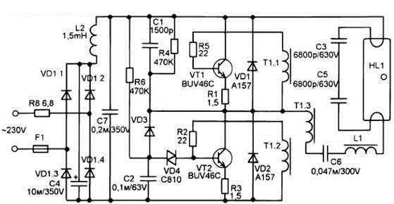
If no problems are found, you need to check the basic elements. For this, it is desirable to have a control gear circuit.
Ballast circuit
The given scheme is typical; it is used in almost all ballasts with slight modifications.

Designations:
- Resistance: R1 - from 1 to 30 Ohms (plays the role of a fuse); R2 and R3– from 220 kOhm to 510 kOhm; R4 and R5– from 1 to 2.7 Ohms; R6 and R7– from 8.2 to 20 Ohms.
- Capacities: C1 - 0.1 uF; C2 - from 1.5 μF to 10 μF 400V; C3 - 0.01 uF; C4 - from 0.033 mF to 0.1 μF 400V; C5 - from 1800 pF to 3900 pF 650V.
- Diodes: VD1-VD5 - 1N4005; VD6 and VD7 are 1N4148.
- Dinistor VS1 - DB3 (may not be used in low-power lighting devices).
- Transistors: VT1, VT2 - 13003 (other analogs are quite possible).
Coil L1 together with capacitor C1 plays the role of a noise filter, in many inexpensive Chinese devices a jumper is sealed instead.
The L2 coil can have from 250 to 350 turns, which are wound with a wire Ø 0.2 mm on a ferrite core having a U-shaped. In appearance it resembles a small transformer.
T1 transformer in each winding from 3 to 9 turns, as a rule, a wire of Ø 0.3 mm is used. A ferrite ring is used as a magnetic circuit.
Fuse: FU1 - 0.5 A. In most products made in China, it is not installed. In such cases, the low-resistance resistance R1 plays the role of a fuse. That it burns in the first place. As a rule, the replacement does not give a result, since its failure is the result of a malfunction, and not the cause.
Ballast troubleshooting
The algorithm of actions will be as follows:
- You need to start by replacing the safety resistor, with problems with the ballast, it almost always burns out.

Safety resistor marked in red
- After the replacement, we begin the search for faulty components. In the above diagram, capacities most often fail, it is from them that it is necessary to start the test. To do this, we arm ourselves with a soldering iron and solder the capacitors C3-C5 (see the circuit in fig. 5). After that, we check them with a multimeter (how to check various electronic components can be found on our website).
Note that in those cases when the lighting device is out of order, but a small glow of the bulb in the filament area, we can say with confidence - replacement is necessary capacity C5. As can be seen from the circuit, it is part of the oscillatory circuit necessary for the formation of a high-voltage pulse in order to cause a discharge. With a burnt capacity, the voltage for the discharge is not enough, as a result, the lamp cannot go into the phase of the operating mode, but power is supplied to the spirals. This is manifested in the form of a small glow.
- If everything is in order with the capacitors, you should test the diodes that make up the bridge. In this case, testing can be done without soldering from the board. If at least one of them is out of order. The probability is high that capacity C2 will be broken.

Electrolytic capacitor C2 is marked in red
Accordingly, if C2 swelling was detected during an external examination, the probability of failure of one or more bridge diodes is high.
- If the items listed are correct, then transistors should be checked. They will have to solder the problem, since the harness will not allow accurate measurements. As practice shows, during the above stages of testing, a malfunction will be detected.
- Having found a malfunction, it is necessary to test the operation of the lighting device by applying power to the base. This must be done carefully, since there is a high voltage on the elements of the board.
After the lamp is lit, turn it off and proceed to assembly. As a rule, there are no problems with it.
Lamp repair with a blown filament
You must immediately warn that such repairs will lead to the fact that the ballast will work in an emergency mode. As a result of overload, the ballast will fail. As a rule, it works in this mode for no more than a year, the duration depends on the elements involved in the circuit and their condition.
If only one filament burns out, it must be shunted with resistance, as shown in the figure.

As shunt resistance RW theoretically, it is necessary to install a resistor with a rating corresponding to the resistance of the second (whole) filament. But, as practice shows, this is not entirely true, because we measure the resistance of the "cold" thread. As a result of such repairs, the device will fail within 10-15 minutes, “burning” with most of the active components. Therefore, we recommend using a resistor of 22 Ohms with a power of at least 1 Watt.
- How to choose LED lamps for home and apartment?
- What are sodium lamps and where are they used?
- How to make a do-it-yourself nightlight
- How to make lighting in the garage with your own hands?


