Would you agree that when designing and installing gas equipment, the parameter that deserves special attention is the working pressure? Since only if the required values are observed and this characteristic is constantly adjusted, safe operation of the gas system is possible.
Stabilization and reduction of the pressure of the gas in the storage tank is provided by a reducer for gasholder, therefore the regulator is an integral part of the system: "gasholder - gas consuming devices ".
Self-installation or replacement of a gas reducer in an autonomous gas supply system at home requires certain skills and knowledge. You need to know what the regulating device consists of and how it works. Therefore, we propose to understand the principle of the gearbox, the subtleties of adjustment and the nuances that arise when replacing it.
The content of the article:
- Purpose and design of the gas tank reducer
- The principle of operation of the stabilization device
- How to adjust the gas regulator?
- Regulator replacement instructions
- Conclusions and useful video on the topic
Purpose and design of the gas tank reducer
For the supply of gas to summer cottages, cottages and private houses are used gasholders. Despite this, a gas pressure regulator with a pressure gauge and a safety valve is an integral part of the system for storing and supplying blue fuel.
The gas reducer performs a function similar to that of a stabilizer in an electrical network. It stabilizes the pressure of the gas flowing from the tank to the equipment. In addition, its tasks include maintaining a certain pressure, obtained at the outlet from the reservoir, throughout the engineering network.
There is no need to skimp on the stabilizer. The device for the gas tank should be of the highest quality, since 80% of the problems in the system arise due to the breakdown of the reducer
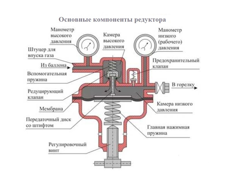
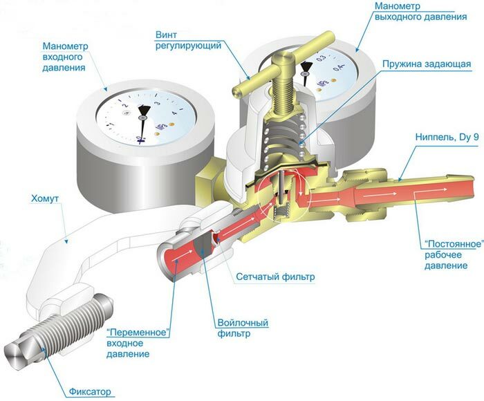
The work of any reducer is aimed at lowering the pressure of liquefied gas, so all pressure stabilizers have the same elements:
- frame;
- two gas chambers;
- inlet and outlet fitting;
- main and auxiliary springs;
- reducing and safety valves;
- membrane;
- transfer disc with pin;
- one or two pressure gauges;
- adjusting screw.
Gearboxes can differ in weight and dimensions, body shape and throughput.
The principle of operation of the stabilization device
Modern pressure reducers for gasholders work on the principle of reverse action. Gas coming from the inlet rod tends to close the pressure reducing valve.
The adjusting screw compresses the main spring and when air escapes from the working chamber, the flexible diaphragm understands the transfer disc with the pin up. At this moment, the pin compresses the return spring, removing the reducing valve from the seat, the gas enters the working chamber.
Two-stage reducers are less susceptible to "freezing"; therefore, such devices must be installed on gas tanks in regions where extremely low air temperature values are noted
After moving the substance into the low pressure chamber, the gas is released into the system. As a result, the spring relaxes, the transfer disc with the pin lifts the valve, the gas from the upper chamber enters the low pressure chamber, the process is repeated.
With a decrease in gas release, the pressure in the chamber will increase, the spring will assume the “closed” position, the valve will sink into the seat, the gas supply to the reducer and the low pressure chamber will stop.
To stabilize the pressure of the gas in the gasholder, two-stage reducers are used. The fuel in such regulators goes through two stages of reduction before entering the outlet fitting.
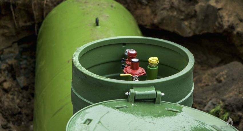
To increase the life of the gearbox, it is necessary to minimize the contact of the membrane and other elements with moisture. For this, at the stage of installation, decorative or standard protection is installed above the tank.
Two stages of the reducer ensure maximum stability of the outlet pressure, therefore they are safer during operation.
In addition, the two-stage devices are frost-resistant, so they provide a continuous supply of gas in summer and winter. If the gearbox is still frozen, we recommend reading our other article, where we described in detail how to fix this problem. Read more - read Further.
How to adjust the gas regulator?
The factory settings of the gas outlet pressure in the reducers may differ from the optimum for the given network, therefore, direct adjustment of the working pressure in the gas tank reducer occurs when it installation. The physical value depends on the tension of the main compression spring, which changes when the position of the adjusting screw is changed.
In two-stage stabilizers, the adjusting screw can only be located on the first stage of the gearbox. These devices include models: Cavagna Group type 524, GOK PS 16 bar POL x IG G1 / 2 PSK CIS, SRG 7.5 kg / h.
In some more expensive models of the Italian company Cavagna Group, German GOK, American Fisher, the second stage of the regulator is also equipped with an adjusting screw.
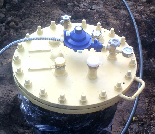
Reducers for gas holders are presented on the market, in which one working unit intervenes a combination of two reduction stages. Equipped with the same control and safety systems, it provides an outlet pressure of 37-50 mbar.
Both stages of the high pressure regulator can be selected separately, then the configuration of the stages can be selected by the user independently. In this case, gas reducing devices connected to the complex valve always have a pressure adjustment screw, and the second stage can be either with a screw or without a screw.
Popular variable second stage gearboxes are Cavagna Group devices, type 992, 998, 998-4.
The first stage of pressure regulation takes place on the gas vapor sampling valve by means of a built-in pressure gauge. Then the gas enters the gearbox chambers. If they do not include control devices, pressure gauge installed directly on the outlet pipe.
In almost all gas tank reducers, the outlet pressure is adjusted using a screw. The adjusting screw is turned with a wrench through the hole located under the removable gear cover.
Clockwise turns increase the outlet pressure, counter-turns decrease.
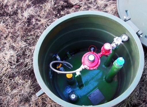
In addition to the pressure gauge and the screw, the safety valve maintains the optimum state of the system. If the pressure in the chambers rises above the norm, then through it there will be an emergency discharge of gas into the atmosphere
At the outlet of the tank, after the gas vapor phase extraction valve, the substance enters the first stage reducer, the stabilizer converts high pressure in the range from 0.2 to 4 bar, depending on the model devices.
The second stage reduces the stable pressure required for the operation of the connected equipment, equal to 10-200 mbar.
Regulator replacement instructions
Two-stage gearboxes are connected to the vapor phase take-off valve using a threaded fitting and a union nut. The type of thread at the inlet of the reducer depends on the type of thread at the outlet of the valve.
If the nature of the connection was not taken into account during the purchase, an appropriate adapter will be required. Connecting the device with gas hose, is carried out through a threaded outlet on the gearbox, using an adapter or union nut.
A gas wrench is required to replace the stabilization device. If the connection is rusted, then two adjustable gas wrenches are required to remove the gearbox.
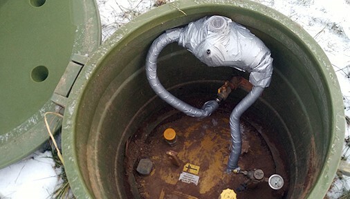
The replacement or repair of the gas reducer is more often carried out in winter, when the formed condensate freezes at the junction of the valve and the reducer. To prevent such malfunctions, at the stage of installing the gas system, it is necessary to provide for electric heating.
To replace the gas regulator, the following sequence of work must be performed:
- Shut off the gas supply with the valve located on the gas vapor phase take-off valve.
- Unscrew the metal hose.
- Unscrew the union nut connecting the valve and the stabilizer.
- Remove the gearbox with connecting hose.
- If the stabilizer cannot be repaired, the bellows hose must be twisted.
- After removing ice, repairing or replacing the regulator, screw the regulator to the complex valve with a nut.
- If the device was disconnected from the supply line, it is necessary to gradually connect the gas hose, first to the reducer, then to the line.
- After fixing the connections, you can turn on the gas supply.
When starting the fuel into the system, after replacing the fittings, it is necessary to check the outlet pressure, it must be within the permissible limits and be suitable for the operation of the heater, stove or boiler.
With correct installation and normal operating conditions, the regulator will typically last at least 10 years.
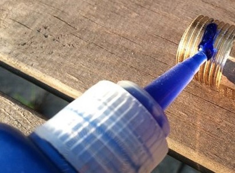
For high strength thread sealing, it is recommended to use blue anaerobic sealant. The material should not be used at low temperatures due to the extended cure time, but if the joints are treated in the summer, they can be 100% sealed.
You can diagnose problems with the stabilizer using a level gauge and a pressure gauge on the tank. If the devices show that there is enough gas, but there are network outages, then one of the gearbox malfunctions is to blame.
In this case, the device can be disassembled and dried. This will help solve the problem, but temporarily. If you install a new gearbox and protect the device from moisture, you can forget about interruptions in the system.
In order to avoid possible problems with the reducer in the future, it is also important to take care of the correct installation of the gas holder on the site. You can read how to do it correctly. here.
Conclusions and useful video on the topic
This is how the gearbox is adjusted using a differential pressure gauge:
This video shows how to eliminate minimum condensate freezing in the regulator:
How to remove, disassemble and clean the gearbox, as well as prevent its flooding / freezing, will be discussed in the following video:
A pressure reducer for a gas holder, reduces the vapor pressure of blue fuel, maintains its stable value in the engineering network. Each regulator is equipped with a safety relief valve that relieves excess gas in the event of a dangerously high fuel outlet pressure from the safety circuit.
Therefore, it is the gearbox that is the main mechanism for preventing emergencies in an autonomous gas supply system.
In the event of a malfunction, you need to know how the device works and how to replace the unusable device. Therefore, the rules for replacing the gearbox will certainly come in handy for the owners of private houses, who have gasified their houses from a gas tank.
If you had to install, change the gas regulator or regulate the gas pressure in an autonomous system. If you know any subtleties and nuances that arise during the replacement of the stabilizer, be sure to share your experience and current photos with readers in the block below.
