DIY welding inverter repair
Today, most household welding units are small in size and weight. This opportunity appeared due to the use of inverter control circuits in their electrical part and converting the welding current, which made it possible to get rid of the switching of the welding windings transformer.
In the electronic circuits of inverter units, powerful field-effect transistors or controlled diodes - semistors and thyristors - are installed to adjust the value of the welding current and switching the voltage.
In order to determine the cause of a malfunction or poor performance of the welding machine and to outline ways to repair it, you must have at least a general idea of its circuitry and principle work.
Content:
- The principle of operation and design of the device ↓
- Reasons for the failure of inverter welds ↓
- Main types of defects ↓
- Basic repair rules ↓
- Power block repair ↓
- Repair of the control unit ↓
- Do-it-yourself safety when repairing a device ↓

The principle of operation and design of the device
A household welding inverter must generate and have at the output a constant current of a certain strength, the value of which is sufficient to ignite and maintain a stable arc burning.
Unlike conventional welding transformers, which simply lower the mains voltage, and rectifier units, inverter equipment are used to convert it to constant voltage converts an alternating voltage with a frequency of 50.0 hertz into a higher frequency, which can significantly increase the stability of the output parameters and use smaller step-down transformers dimensions.
The process of obtaining the parameters necessary to ensure the metal welding process includes the following sequential procedures (operations):
- rectification of mains voltage;
- converting it into high frequency current;
- lowering the voltage to the required level at which a sufficient value of the output current is provided;
- re-straightening voltage.
To convert low-frequency mains voltage into high-frequency voltage, special converters are used, built on the basis of powerful transistors. The rectification of the final voltage is carried out by bridge devices based on powerful diode assemblies or thyristors (semistors).
Household inverters in their design contain several functionally related blocks, which are located on separate boards and are connected by means of conductors or loops to each other.
The main element of the inverter is the power unit, on which the following modules are installed:
- Primary rectifier unit, which is a board on which powerful diodes are installed in a bridge circuit.
- The inverter converter is based on a powerful transistor that generates high-frequency voltage with a frequency of 50.0... 100.0 kilohertz.
- The voltage lowering module includes a transformer with tape windings that decreases the voltage to 40.0... 50.0 volts.
- The output rectifier is assembled on the basis of diodes designed for currents up to 250.0 amperes.
- All power elements (diodes and transistors) are installed on cooling radiators (heat sinks) and the device body is equipped with a forced ventilation system.

Reasons for the failure of inverter welds
As a rule, a malfunction of an inverter welding machine occurs due to non-observance or violation of operating rules. Quite often, breakdowns are caused by moisture entering the electronic parts of individual modules.
The high-frequency voltage creates an electrostatic field, which contributes to the accumulation of dust, which cannot be removed by the ventilation system. Dust leads to a change in the resistance parameters in certain areas of the electronic circuit boards, which also causes a malfunction of the entire unit.
An inexperienced welder can damage the inverter if he performs welding work for which the machine is not designed. For example, cutting a channel profile with a low-power household device will lead to its overload and guaranteed breakdown. If reliable contact of the network and welding cables is not ensured, overheating of the contact zone and destruction of terminal insulators will be observed.
In addition to operational disturbances, the inoperability of inverter welding can be caused by reasons that do not depend on the qualifications of the welder and the nature of the work performed. This is, first of all, a decrease in the mains voltage to the level of 180.0... 190.0 volts, which is a fairly frequent phenomenon in summer cottages and rural settlements.
We must not forget about low-quality assembly and the use of low-quality components, which is the main reason for the failure of unprocessed in production and untested in operation welding inverters.
Main types of defects
Consider the main malfunctions that the owner of an inverter welding machine most often encounters. If there is no voltage at the output of the device, this is usually caused by blown fuses or a violation of the integrity of one of the conductors in the device circuit.
The second fairly common malfunction is manifested in the inability to set the desired value of the welding current even in the extreme, maximum position of the power regulator. The reason for this defect is, as a rule, a reduced supply voltage level.
If the device spontaneously turns off quite often during operation, you should check whether its modules overheat. The second reason for the shutdown may be the presence of a short circuit in any elements of the device circuit.
The instability of the welding arc is caused by malfunctions of either the power unit or the control module. If the unit generates an increased noise level during operation, this is an indication of overloading, which can lead to more serious malfunctions.
In the presence of defects in the operation of the protection system, the consequences can be the most unpredictable. Unfortunately, usually the malfunction of this module is detected too late, when the malfunction has reached a critical level and any part of the device has failed.

Basic repair rules
The malfunction of the welding inverter is not always problematic and may well be eliminated by its own hands by a person who has certain electrical skills and is able to understand the intricacies of circuitry products. Before you start disassembling the device, you should check the reliability of the contact of the input and welding cables.
Any repair should begin with a visual inspection of the “internals of the unit”. The presence of mechanical damage on printed circuit boards, charring or blackening of the conductor insulation, traces of a short circuit indicate a possible malfunction. If it is not possible to visually determine the cause, you should use a multimeter to check the integrity of the connecting conductors between the individual units of the unit.
If this is not the case, and the cause of the malfunction is of a more serious nature, you should proceed to a more thorough diagnosis of the product. This may require the following tool:
- pliers with insulated handles;
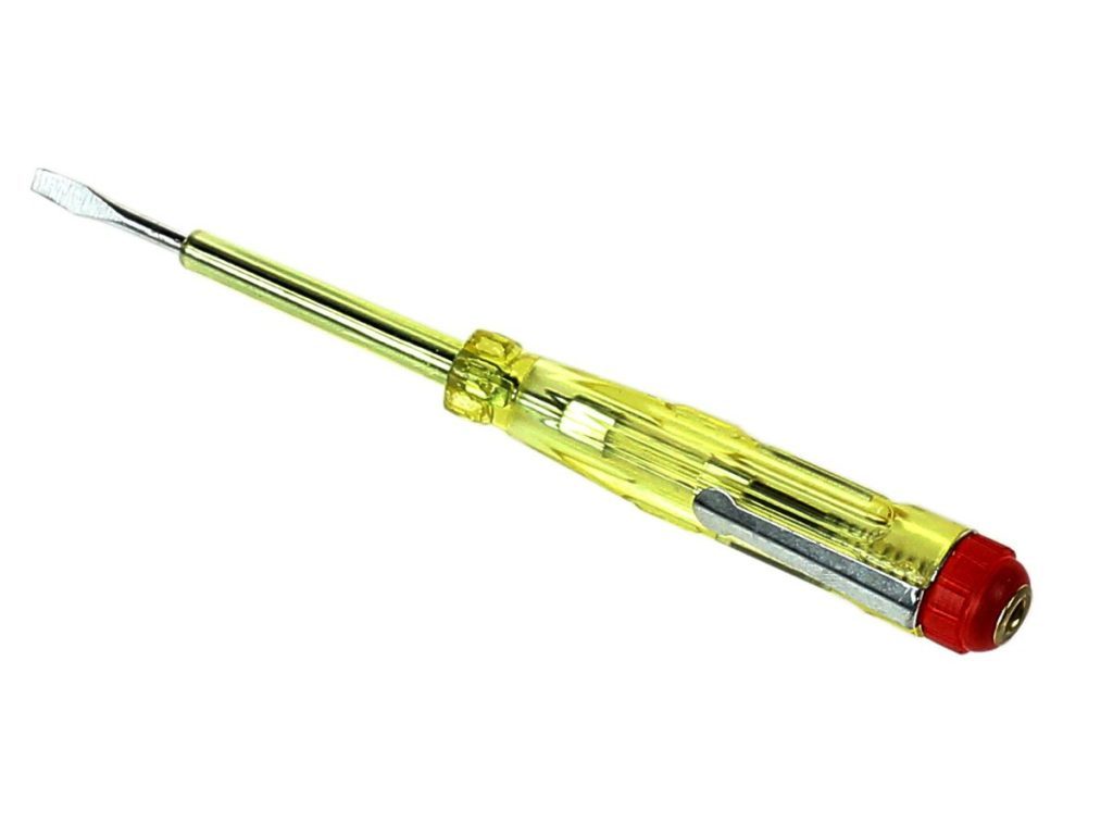
- a set of straight and Phillips screwdrivers;
- an electric soldering iron with a capacity of 40.0... 100.0 watts;
- set of open-end and socket wrenches
- nippers;
- locksmith's knife;
- multimeter (tester with measurement limits of 50.0... 250.0 volts;
- ammeter with measurement ranges of 0... 50.0 and 0.250 amperes.
Some experts may say that without an oscilloscope and a frequency meter, many reasons for the failure of individual units of the welding machine cannot be determined. However, these reasons are quite specific, and elimination is quite difficult. To repair a device with similar defects, you should contact the specialists of the repair firms.

Power block repair
The main reason for the failure of the power unit is the failure (burnout, breakdown) of a powerful transistor. In most cases, its malfunction can be determined visually. The transistor case may have deformations (swelling, ruptures), darkening, burnouts. Repair consists in replacing the defective part. Before installing the new transistor on the radiator, the place from the contact should be greased with special thermal grease.
Usually, a power triode does not fail alone, but is accompanied by burnout of microcircuits and transistors of the control circuit. The repair of the device in this case also consists in replacing the failed parts.
Breakdown or burnout of power bridge diodes is more rare. However, before starting to replace the power transistor, the diodes should be ringed with a multimeter, determining their resistance. Zero or infinitely high resistance of one of the diodes, when alternately connecting the multimeter probes of different polarity, indicates a malfunction of the electronic device under test.
When replacing diodes and transistors, their full analogs should be selected, up to the correspondence of the letter index, which characterizes the speed of the electronic element.
Repair of the control unit
"Home" repair of the control unit consists in a visual inspection of the module parts and checking the conductors for a break.
If this is not the cause of the malfunction, then it makes sense to contact a specialized repair organization. This will not only cost less, but also guarantee that the replaced electronic circuit parts will not fail again.
If, when the unit overheats, it does not turn off automatically and the warning light does not come on (not available on all models), check the reliability of the connection of the thermal switches with the sensors temperature. Eliminate the malfunction by replacing one of these items.

Do-it-yourself safety when repairing a device
Modern welding household welding inverters are quite reliable in operation, and during their periodic maintenance and repair, certain rules should be observed:
- Do not use the product with the cover removed.
- All diagnostic work and replacement of parts are performed on a completely de-energized device.
- When removing dust accumulated inside the housing, a jet of compressed air is used at an excess pressure not exceeding 5.0 atmospheres.
- Cleaning of printed circuit boards and electronic components located on it is performed with a brush (like a shaving brush).
- Long-term storage of the device is carried out only in a dry room, with a completely closed case and disconnected from the mains.


