The classic household (split) air conditioning system has several electric motors. Plus, manufacturers of this kind of equipment provide in advance for the execution of the connections of all electric motors that make up the structure. Therefore, only a small part of the work with the electrical circuit remains for end users.
In this article, we will consider in more detail what and how a potential owner of the equipment needs to do, to correctly connect the air conditioner motor and start the equipment in work. We will also talk about the features of the split system scheme, give illustrative photos and useful video materials.
The content of the article:
-
Household split system diagram
- Air conditioner design features
- Bundle of indoor and outdoor modules
-
Motor connection instructions
- Stage # 1 - connecting the outdoor unit
- Stage # 2 - connecting the indoor unit
- Stage # 3 - connecting two system modules
- Conclusions and useful video on the topic
Household split system diagram
The split system is traditionally used in everyday life for air conditioning. True, in addition to this version of household air conditioners, other designs are also used. However, as practice shows, the operation of another type of climatic equipment is noticeably less common.
Air conditioner design features
What is, from a structural point of view, a household split system?
Actually, this is air conditioning equipment, consisting of two separate modules (blocks):
- Block for internal installation.
- Block for external installation.
Under internal installation implies the installation of one part of the air conditioner structure (unit for indoor installation) directly inside the room, where the processing of ambient air is required.
Accordingly, under external mounting implies the installation of another part of the air conditioner structure (block for external installation), directly outside the room. As a rule, installation in this case is carried out on the street side of the wall of a house or premises for other purposes.
But first, we recommend that you familiarize yourself with where you can put the air conditioner in a private house and apartment.
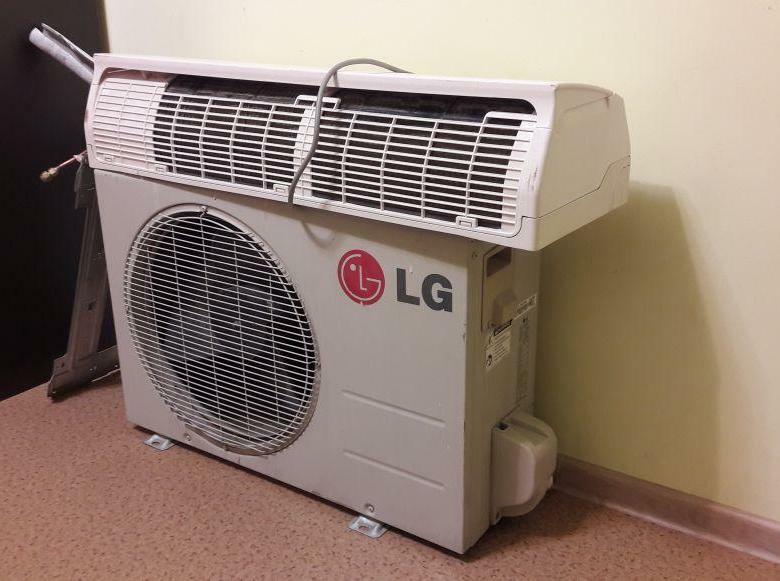
A classic example of a split system (domestic air conditioning units), structurally consisting of two separate modules - outdoor and indoor
Bundle of indoor and outdoor modules
In the next step, the user needs to link both modules into a single working system.
It provides for the linking of modules by mechanical part piping for refrigerant circulation, as well as binding along electrical part electric cable, respectively. This process is called laying the air conditioner route.
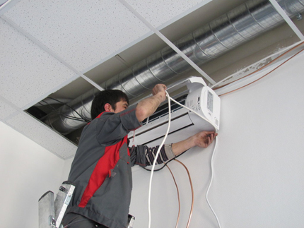
Connection procedure on modules (indoor module of split system shown) refrigerant piping as well as electrical conductors
In fact, a household air conditioner contains several functional electric motors, each of which requires power supply:
- compressor motor;
- outdoor unit fan motor;
- indoor unit fan motor.
In addition, the air conditioning system can be additionally equipped with electric motors, the operation of which sets the shutters in motion, directing the outgoing air flow in the desired direction.
Louvers for regulating the outgoing air flow are usually part of the structure of the indoor unit of a domestic air conditioning unit.
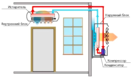
Demonstration of a fully assembled split system with the installation of indoor and outdoor units, combined into a single structure by means of technological connections
Depending on the power level of the outdoor unit of the air handling unit, two or more condenser cooling fans (installed in the outdoor unit) can be used.
True, for household climatic equipment, such options are rare. But for use in offices, split systems for two fans are quite common.
Motor connection instructions
Now let's take a closer look at how to properly connect the motor of a household air conditioner. So, manufacturers of household air conditioners provide the most convenient option for connecting equipment to the power supply network. Moreover, a simplified connection diagram is provided for both single-phase and three-phase networks.
It is not necessary to directly connect the air fan of the outdoor unit of the air conditioner. It is enough to connect the common (main) power supply and commutation cable to a special terminal. But first, we recommend that you figure out how select and install a vending machine on the air conditioner.
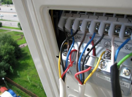
View of the contact terminal for connecting the air conditioning system after the open protective cover. In this case, a three-phase connection is demonstrated, which is not often used in everyday life.
To figure out how to properly connect the electric motor from the air conditioner to the power supply and understand the subtleties of connecting conductors on the switching terminal, consider the electrical circuit of one of devices.
Wiring diagrams for connecting household air conditioning units have minor differences. Any manufacturer of this kind of machine is interested in competition even in terms of the convenience (simplicity) of the electrical connection.
Stage # 1 - connecting the outdoor unit
An important detail should be noted right away: the electrical circuit for switching modules and connecting to the mains is always present on the back of the protective terminal cover.
In any case, well-known manufacturing firms adhere to this practice. In addition, the electrical connection diagram is always included in the device documentation.
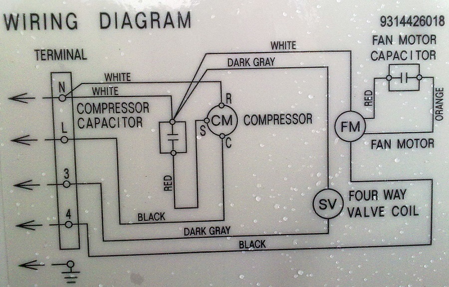
Example of wiring diagram on the terminal cover of an outdoor unit for a domestic air conditioning system. Here is a single-phase version, where the terminals are connected to the terminal: N - neutral (zero); L - phase; 3, 4 - terminals of conductors for interfacing with the indoor unit; also on the diagram there is a "ground" contactor
In the above connection diagram, you can clearly see the presence of two electric motors present in the outdoor (outdoor) module.
This, respectively, compressor motor (CM) and condenser fan motor (FM). Schematically, the power lines of both electric motors are commutated and brought out to the terminal.
Stage # 2 - connecting the indoor unit
The split system module, designed for indoor installation, also has a switching terminal through which electrical communication with the outdoor module is carried out. Power is supplied to the indoor unit via the same terminal.
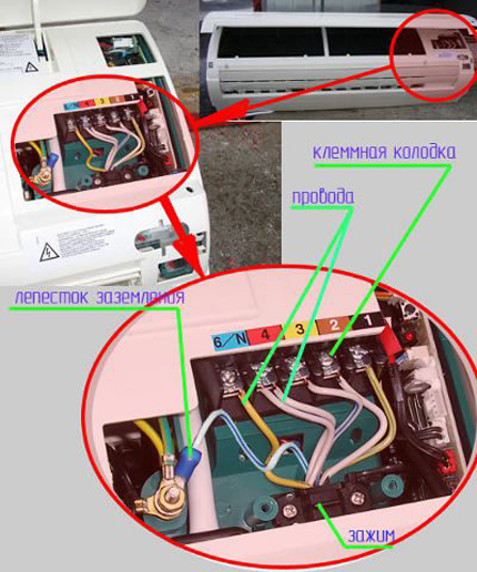
Example of location of a breakout terminal for an indoor air conditioning module. It should be noted - for products of different companies, the design and location may differ slightly.
Usually, in the simplest version, a signal pair of conductors is connected to the terminal of the indoor module, as well as:
- phase;
- null;
- grounding.
Again, depending on the design of a particular brand's A / C system, the electrical connection configuration may look different.
Therefore, you should always carefully read the technical documentation before proceeding with the installation work.
Stage # 3 - connecting two system modules
So, let's assume that both modules of the air conditioning system are mounted inside and outside the building - fixed on the wall panels:
- a refrigerant circulation line is laid between the modules, consisting of two copper pipes of different cross-sections;
- main pipes are insulated and secured;
- the end points of the main pipes are appropriately connected to the modules;
- the installed line is checked for tightness with a time delay.
After performing this sequence of operations with the newly installed household air conditioner, you can already start organizing electrical communication between the modules with subsequent connection directly to the network nutrition. One of the possible options for connecting blocks is shown in the diagram below.
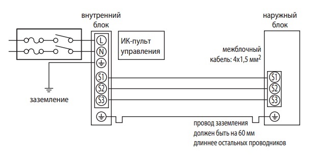
A variant of a schematic diagram showing the integration of individual modules of a household air conditioning system into a single electrical system. But this example, unfortunately, is not applicable to all models of split systems without exception.
Actually, as can be seen from the above configuration of combining modules with each other, there are no special difficulties in the work for the user. Just follow the numbering (or designation) of the terminals when making connections between the terminals of the indoor and outdoor units.
That is, if an electric wire is connected to the terminal marked “1” on the outdoor unit, the same wire is also connected to the terminal “1” on the indoor unit, and so on.
Of course, the execution of electrical interconnections, as well as connections to the supply network, must be done taking into account the correct selection of conductor cross-section. The permissible cross-sections are usually indicated in the documentation for the device in the same section where the circuit diagram is presented.
We also recommend that you familiarize yourself with the features of the choice space for the installation of the socket for the air conditioner.
Conclusions and useful video on the topic
Thus, the connection of the air conditioner electric motor (more precisely, the technological connection of the household air conditioning unit) is quite accessible to the user himself. The video clearly demonstrates the following procedure:
A home craftsman who decides to connect an air conditioner motor must have the basics of working with refrigerants, plus have an idea of electrical networks. It is desirable, of course, to have some experience in such matters. If there is absolutely no idea about the work of such a plan, the best way out is to contact the service.
Do you have personal experience of connecting a household discussion electric motor and want to share it with other users? Or would you like to clarify certain nuances of electrical connections with our experts? Write your recommendations, ask questions - the feedback block is located below this publication.


