The use of water as a coolant in the heating system - one of the most popular options to ensure your house warm during the cold season. It is only necessary to properly design and then perform the installation of the system. Otherwise, the heating will be ineffective in the high cost of fuel, which will agree, it is not interesting at today's energy prices.
Implement their own water heating calculation (hereinafter - CBO) is impossible without the use of specialized software, as used in the calculations complex expressions to determine the values of which by a conventional calculator it is impossible. In this article, we analyze in detail the algorithm performing calculations, give a formula used by considering the implementation of a specific example of calculations.
The material complete the table with the values and reference parameters that are needed during the computing themed photos and videos, which demonstrated a clear example of the calculation by the use of programs.
The content of the article:
-
Calculation of the heat balance housing structure
- Calculation of heat loss through OK
- Heat ventilation costs
-
Example of calculation of the thermal balance
- Step # 1 - Calculation of heat loss walls
- Step # 2 - TP calculation of windows and doors
- Step # 3 - Definition TP floor and ceiling
- Step # 4 - Calculation of ventilation TP
-
Features of the calculation of NWO
- Ring main circulating GH
- GR secondary circulation ring
- Calculation of radiator panels
- Conclusions and useful videos on the topic
Calculation of the heat balance housing structure
For the introduction of a heating installation, where the circulating material protrudes water previously required to make exact hydraulic calculation.
When developing, implementing any type of heating system you need to know the thermal balance (hereinafter - TB). Knowing the heat output to maintain the temperature in the room, you can choose the right equipment and to distribute its load properly.
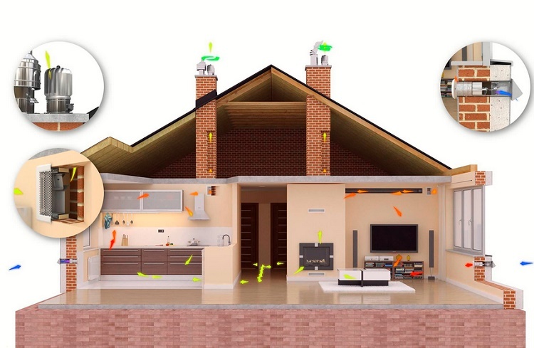
In winter, the room has a certain heat loss (hereinafter - TP). The main mass of energy goes through the building elements and the ventilation openings. Minor expenses accounted for infiltration, heating and other items.
image gallery
Photo of

Competent calculation of water heating, by analogy with other types of systems required for the selection of a heating unit capable of fully compensate the heat loss

The calculations are summarized all kinds of losses through the building envelope, leakage through the door and window openings

The power of computing equipment should take into account the need to heat the air entering the room during the airing and through tightly closed sash windows and door panels

The heating is considered mandatory airflow supplied with fresh air forced ventilation function mix with fresh air partial portions

When the bypass circuit in the heating boiler in calculating real power includes the energy spent for heating hot water

Properly performed calculations suggest to determine the effectiveness of the heating unit and the fuel used

Most heating circuits within the heated space are laid open, except structurally arranged in the floor or walls of this. In closed circuits must take into account the energy for heating designs

In an open heating circuits, direct contact with the atmosphere via the expansion tank is taken into account the loss of coolant in the cooling

Performing the calculation of water heating

Loss through structures

Accounting for heating the incoming air

Ventilation mix with fresh air

Allowance for loss of the preparation of hot water

The calculation of the efficiency of the processed fuel in the boiler

One embodiment of a heating circuit device

with an open expansion tank system
TS depend on the layers that make up the building envelope (hereinafter - OK). Modern building materials, in particular heaters, have low thermal conductivity (Further - CT), so through them leaves less heat. For the houses of the same area, but with a different structure OK, heat costs will be different.
In addition to determining the TA, it is important to calculate TB home. The indicator takes into account not only the amount of energy leaving the room, but also the number of necessary power to maintain a certain degree of measures in the home.
The most accurate results provide specialized programs designed for builders. Thanks to them, may take into account more factors affecting the TA.

The greatest amount of heat leaves the room through the walls, floor, roof, the smallest - in the door and window openings
With high accuracy can be calculated TA housing via formulas.
General home heating expenses are calculated according to the equation:
Q = Qok + Qv,
Where Qok - the amount of heat leaves the room through OK; Qv - thermal ventilation costs.
Losses through ventilation captured in the event that the air entering the room, has a lower temperature.
The calculations take into account the generally OK, entering one side of the street. This exterior walls, floor, roof, doors and windows.
General TP Qok equal to the sum of each TP OK, that is:
Qok = ΣQst + ΣQokn + ΣQdv + ΣQptl + ΣQpl,
Where:
- Qst - the value of TP wall;
- Qokn - TP window;
-
Qdv - TP doors;
-
Qptl - TP ceiling;
- Qpl - TP floor.
If the floor or ceiling structure is unequal across the area, the TP is calculated for each section separately.
Calculation of heat loss through OK
For the calculation you need the following information:
- Wall structure, the materials used, their thicknesses, CT;
- the ambient temperature is extremely cold winters in five days;
- OK area;
- Orientation OK;
- recommended temperature in the dwelling in winter.
To calculate the TA needed to find the total thermal resistance ROK. To do this, you need to know the thermal resistance R1, R2, R3,..., Rn each layer OK.
coefficient Rn calculated using the formula:
Rn = B / k,
In the formula: B - OK layer thickness in mm, k - CT of each layer.
Total R may be determined by the expression:
R = ΣRn
Manufacturers of doors and windows usually indicate the R factor in the passport of the product, so count it separately is not necessary.

Thermal resistance of windows, you can not count, because in the data sheet are already present the necessary information, which simplifies the calculation of the TP
The general formula for calculating the TA through OK as follows:
Qok = ΣS × (tvnt - tnar) × R × l,
In the expression:
- S - OK area, m2;
- tvnt - the desired temperature in the room;
- tnar - external air temperature;
- R - drag coefficient is calculated separately from the passport or taken products;
- l - refinement coefficient reflecting the orientation of the walls relative to the cardinal points.
TB calculation makes it possible to choose the equipment necessary power that will eliminate the likelihood of heat shortage or oversupply. heat deficit is compensated for by an increase in air flow through the ventilation overabundance - installation of an additional heating equipment.
Heat ventilation costs
The general formula for calculating the TA ventilation is as follows:
Qv = 0.28 × Ln × pvnt × c × (tvnt - tnar),
In terms of the variables have the following meanings:
- Ln - the cost of incoming air;
- pvnt - air density at a certain temperature in the room;
- c - specific heat of air;
- tvnt - the temperature in the house;
- tnar - external air temperature.
If ventilation is installed in a building, the parameter Ln Performance is taken from the device. If the ventilation is omitted, the standard measure of specific ventilation equal to 3 m3 in hour.
On this basis, Ln calculated as follows:
Ln = 3 × Spl,
In the expression Spl - floor area.

2% of all heat loss accounts for infiltration, 18% - for ventilation. If the room is equipped with a ventilation system, the calculations take into account TP through ventilation and infiltration in mind do not take
Next, we must calculate the air density pvnt at room temperature in a predetermined tvnt.
This can be done using the formula:
pvnt = 353 / (273 + tvnt),
Specific heat c = 1.0005.
If ventilation or unorganized infiltration in the walls there are cracks or holes, the calculation of the TA through the holes should be entrusted to special programs.
In another article, we brought our detailed an example of the calculation of heating with concrete examples and formulas of the building.
Example of calculation of the thermal balance
Consider the house height of 2.5 m, a width of 6 m and 8 m long, located in Oxa Sakhalin region where extremely cold 5-day's rest thermometer thermometer lowered to -29 degrees.
As a result, the ground temperature was set measurements - +5. Recommended temperature inside the structure is 21 degrees.

Depict the scheme at home it's best on paper, stating not only the length, width and height of the buildings, but also the orientation relative to the cardinal, and the location, the size of windows and doors
The walls of the house under consideration consist of:
- The masonry thickness = 0.51 m, CT k = 0.64;
- The mineral wool m = 0.05, k = 0.05;
- cladding B = 0.09 m, k = 0.26.
In determining the k best to use a table, view the manufacturer's website, or find information in the technical data sheet.

Knowing the thermal conductivity, it is possible to choose the most efficient in terms of heat insulation materials. Based on the above table, the most appropriate to use in the construction of mineral wool and expanded polystyrene
The floor covering consists of the following layers:
- OSB-boards B = 0.1 m, k = 0.13;
- The mineral wool m = 0.05, k = 0.047;
- The cement screed m = 0.05, k = 0.58;
- Styrofoam B = 0.06 m, k = 0.043.
The house has no basement and the floor has the same structure throughout the area.
The ceiling is made up of layers:
- Drywall sheets B = 0.025 m, k = 0.21;
- The heater m = 0.05, k = 0.14;
- Roof coverings B = 0.05 m, k = 0.043.
The outputs of the attic are not available.
The house has a total of 6 two-chamber windows and glass and argon. The data sheet on the product's known that R = 0.7. The windows have dimensions 1.1h1.4 m.
Doors have dimensions 1h2.2 m, figure R = 0.36.
Step # 1 - Calculation of heat loss walls
The walls throughout the area consist of three layers. At first calculate their total thermal resistance.
Why do we use the formula:
R = ΣRn,
and the expression:
Rn = B / k
Given the initial data, we obtain:
Rst = 0.51/0.64 + 0.05/0.05 + 0.09/0.26 = 0.79 +1 + 0.35 = 2.14
Learning the R, you can proceed to the calculation of TP northern, southern, eastern and western walls.

Additional factors take into account the particular arrangement of the walls relative to the cardinal. Typically, in the northern part during cold formed "wind rose", with the result that the TP on this side will be higher than with other
Calculate the area of the northern wall:
Ssev.sten = 8 × 2.5 = 20
Then, substituting into the formula Qok = ΣS × (tvnt - tnar) × R × l and considering that l = 1.1, we obtain:
Qsev.sten = 20 × (21 + 29) × 1.1 × 2.14 = 2354
The area of the south wall of Syuch.st = Ssev.st = 20.
In the wall there is no built-in window or door, so, given the coefficient l = 1, we obtain the following TP:
Qyuch.st = 20 × (21 +29) × 1 × 2.14 = 2140
To the west and east walls of the coefficient l = 1.05. Therefore it is possible to find the total area of the walls, that is:
Szap.st + Svost.st = 2 × 2.5 × 6 = 30
6 windows and a door built into the wall. We calculate the total area of windows and doors S:
Sokn = 1.1 × 1.4 × 6 = 9.24
Sdv = 1 × 2.2 = 2.2
We define S S walls excluding windows and doors:
Svost + zap = 30 – 9.24 – 2.2 = 18.56
We calculate the total transformer substation the eastern and western walls:
Qvost + zap =18.56 × (21 +29) × 2.14 × 1.05 = 2085
After receiving the results, we calculate the amount of heat escaping through the walls:
Qst = Qsev.st + Qyuch.st + Qvost + zap = 2140 + 2085 + 2354 = 6579
Total general TP wall is 6 kW.
Step # 2 - TP calculation of windows and doors
Windows are located on the east and west walls, so when koєffitsient calculations l = 1.05. It is known that the structure of all constructs the same and R = 0.7.
Using the values of area, given above, we obtain:
Qokn = 9.24 × (21 +29) × 1.05 × 0.7 = 340
Knowing that for doors R = 0.36, and S = 2.2, define their TP:
Qdv = 2.2 × (21 +29) × 1.05 × 0.36 = 42
As a result, through the windows out 340 watts of heat, and through the door - 42 watts.
Step # 3 - Definition TP floor and ceiling
Obviously, the ceiling and the floor area will be the same, and is calculated as follows:
Spol = Sptl = 6 × 8 = 48
Calculate the total thermal resistance of the floor because of its structure.
Rpol = 0.1/0.13 + 0.05/0.047 + 0.05/0.58 + 0.06/0.043 = 0.77 + 1.06 + 0.17 + 1.40 = 3.4
Knowing that the soil temperature tnar= + 5 and considering the coefficient l = 1, calculate Q sex:
Qpol = 48 × (21 – 5) × 1 × 3.4 = 2611
Round, we find that the floor heat losses amount to about 3 kW.

The TA calculation is necessary to consider the layers, affecting the thermal insulation, for example, concrete board, masonry, heaters, etc.
We define the heat resistance of the ceiling Rptl and Q:
- Rptl = 0.025/0.21 + 0.05/0.14 + 0.05/0.043 = 0.12 + 0.71 + 0.35 = 1.18
- Qptl = 48 × (21 +29) × 1 × 1.18 = 2832
It follows that through the ceiling and the floor takes almost 6 kW.
Step # 4 - Calculation of ventilation TP
The room ventilation is organized, calculated as follows:
Qv = 0.28 × Ln × pvnt × c × (tvnt - tnar)
Based on the specifications, the specific heat of 3 cubic meters per hour, i.e.:
Ln = 3 × 48 = 144.
For calculating density using the formula:
pvnt = 353 / (273 + tvnt).
Estimated room temperature is 21 degrees.

TA ventilation is calculated if the system is provided with air heating device
Substituting the known values, we get:
pvnt = 353/(273+21) = 1.2
Substituted in the above formula of the figures:
Qv = 0.28 × 144 × 1.2 × 1.005 × (21 – 29) = 2431
Given the TP on ventilation, the total Q of the building is:
Q = 7000 + 6000 + 3000 = 16000.
Translating in kW, obtained general heat loss of 16 kW.
image gallery
Photo of

In the calculations of the heating unit for warm water should take into account the calorific value of fuel - amount of heat generated by the combustion

During the combustion of 1 kg of coal allocated 5600-7000 kcal / kg of heat energy by the combustion of brown analog only 2200-3200 Kcal / kg

Slightly brown coal efficiently cleaved supplying only 2700-3200 Kcal / Kg. However, this is one of the cheapest and affordable fuels

The most beneficial for use in a private household gas releasing 8,400 kcal / Nm³ at its one cubic meter of combustion. It is true when using gas cylinders or gas tank prices will be higher

Inventories of aircraft fuel efficiency

Determination of the amount of heat during the combustion of coal

Capacity when burning firewood

The best option - the use of natural gas
Features of the calculation of NWO
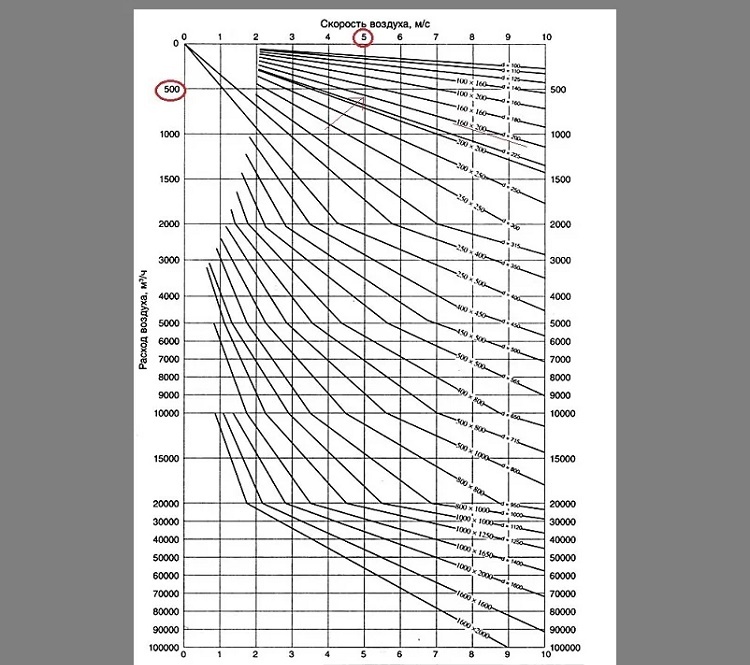
After finding the index TP transferred to the hydraulic calculation (hereinafter - GR).
On its basis, receive information on the following indicators:
- optimal diameter pipes, which will be able to pass a predetermined amount of coolant at a pressure drop;
- coolant flow rate at a certain location;
- rate of movement of water;
- value of resistivity.
Before starting the calculation to simplify the calculations show spatial diagram of a system in which all its elements are arranged parallel to each other.

The diagram shows a system of heating with the upper wiring, the movement of the coolant - deadlock
The main stages of water heating calculations.
Ring main circulating GH
Methods of calculating GR is based on the premise that all branches of the risers and identical temperature changes.
The calculation algorithm is as follows:
- Shown on the scheme, taking into account the heat loss, heat is applied to the load acting on the heaters, risers.
- Based on the scheme selected main circulating ring (hereinafter - HCC). The peculiarity of the ring that it circulating pressure per unit length of the ring takes the smallest value.
- HCC is divided into portions having a constant heat flow. To indicate the number of each portion, thermal load, diameter and length.
In the vertical system of a single tube type is taken as an fcc the ring through which the most loaded stand pipe at a dead end or passing water movement on highways. More details about linking rings circulating in pipe system and the choice of main, we talked the following article. Separately paid attention to the order of performing calculations using a specific example for illustrative purposes.

In vertical systems fcc twin tube type extends through the bottom heating device having a dead end at the maximum load or the movement of water passing
In a horizontal system fcc single pipe type must have the smallest circulation pressure and unit length of the ring. For systems with natural circulation the situation is similar.
When GH downcomer vertical single-pipe type flow system, the flow-adjustable struts, having in its composition standardized nodes is regarded as a single circuit. For risers with trailing portions produce separation, considering distribution of water in each pipe tool assembly.
Water consumption in the given section is given by:
Gkont = (3.6 × Qkont × β1 × β2) / ((Tr - t0) × c)
In terms alphabetic characters have the following values:
- Qkont - thermal load circuit;
- β1, β2 - additional table coefficients taking into account the heat transfer in the room;
- c - the specific heat of water is equal to 4,187;
- tr - temperature of the water in the supply line;
- t0 - the water temperature in the return line.
After determining the diameter and the amount of water necessary to know its velocity, and the value of specific resistance R. All calculations are most conveniently carried out with the help of special programs.
GR secondary circulation ring
After the master ring GR determined pressure in the pulmonary circulation ring, which is formed through it coming risers Considering that the pressure loss can differ by not more than 15% when the stall scheme and not more than 5%, with passing.
If it is impossible to link the pressure loss is set throttle washer, the diameter of which is calculated using software techniques.
Calculation of radiator panels
Let's go back to the plan of the house, located above. By calculation it was found that in order to maintain heat balance is required 16 kW of energy. In this house has 6 rooms for different purposes - living room, bathroom, kitchen, bedroom, hallway, hallway.
Based on the design dimensions, it is possible to calculate the volume V:
V = 8 × 6 × 2.5 = 120 m3
Next you need to find the amount of heat output per m3. To do this, Q should be divided by the volume found, ie:
P = 16000/120 = 133 watts per m3
Next, you must determine how much heat output required for a single room. In the diagram, the area of each room is already calculated.
Determine the amount of:
- bathroom – 4.19×2.5=10.47;
- living room – 13.83×2.5=34.58;
- kitchen – 9.43×2.5=23.58;
- bedroom – 10.33×2.5=25.83;
- corridor – 4.10×2.5=10.25;
- hallway – 5.8×2.5=14.5.
The calculations also need to consider the room in which there is a heating duct, such as a corridor.

Corridor heated in a passive way, it will flow heat by circulating air heat at movement of people through doorways, etc.
We define the necessary amount of heat for each room, by multiplying the amount of room on the indicator P.
We obtain the required power:
- for bathrooms - 10.47 × 133 = 1392 W;
- living Room - 34.58 × 133 = 4599 W;
- for kitchen - 23.58 × 133 = 3136 W;
- bedroom - 25.83 × 133 = 3435 W;
- for the corridor - 10.25 × 133 = 1363 W;
- hallway - 14.5 × 133 = 1889 watts.
We proceed to the calculation of radiator panels. We use aluminum radiators, whose height is 60 cm, power at 70 is 150 watts.
We calculate the required number of radiator panels:
- bathroom – 1392/150=10;
- living room – 4599/150=31;
- kitchen – 3136/150=21;
- bedroom – 3435/150=23;
- hallway – 1889/150=13.
Total need: 10 + 31 + 21 + 23 + 13 = 98 radiator panels.
Our site also has other articles that we reviewed in detail the order of the thermal design of the heating system, step by step calculation of the power of radiators and heating pipes. And if your system requires the presence of warm floors, you will need to perform additional calculations.
More detail all these issues dealt with in our next article:
- Thermal heating system calculation: how to correctly make a calculation on the system load
- Calculation of radiators: how to calculate the required amount of battery power and
- Calculation of pipe volume: principles and rules for the calculation of payments production in liters and cubic meters
- How to make a calculation of floor heating on the example of a water system
- Calculation of pipes for floor heating: types of pipe laying techniques and step-flow calculation +
Conclusions and useful videos on the topic
In video you can see an example of calculation of water heating, which is carried Valtec program means:
Hydraulic calculation is best done with the help of special programs, which guarantee the high accuracy of the calculations take into account all the nuances of design.
Do you specialize in performing the calculation of heating systems using water as a coolant and want to supplement our article useful formulas, trade secrets to share?
Or maybe you want to focus on additional calculations or to point out the inaccuracy in our calculations? Please write your comments and recommendations under Article box.